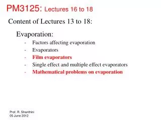
PM3125: Lectures 16 to 18
500 likes | 880 Views
PM3125: Lectures 16 to 18. Content of Lectures 13 to 18: Evaporation: Factors affecting evaporation Evaporators Film evaporators Single effect and multiple effect evaporators Mathematical problems on evaporation. Example 4:

PM3125: Lectures 16 to 18
E N D
Presentation Transcript
PM3125: Lectures 16 to 18 • Content of Lectures 13 to 18: • Evaporation: • Factors affecting evaporation • Evaporators • Film evaporators • Single effect and multiple effect evaporators • Mathematical problems on evaporation
Example 4: Estimate the requirements of steam and heat transfer surface, and the evaporating temperatures in each effect, for a triple effect evaporator evaporating 500 kg h-1 of a 10% solution up to a 30% solution. Steam is available at 200 kPa gauge and the pressure in the evaporation space in the final effect is 60 kPa absolute. Assume that the overall heat transfer coefficients are 2270, 2000 and 1420 J m-2 s-1 °C-1 in the first, second and third effects, respectively. Neglect sensible heat effects and assume no boiling-point elevation, and assume equal heat transfer in each effect. Source: http://www.nzifst.org.nz/unitoperations/evaporation2.htm
500 kg h-1 60 kPa (abs) 10% solution 200 kPa (g) 30% solution Overall heat transfer coefficients are 2270, 2000 and 1420 J m-2 s-1 °C-1 in the first, second and third effects, respectively. Estimate the requirements of steam and heat transfer surface, and the evaporating temperatures in each effect. Neglect sensible heat effects and assume no boiling-point elevation, and assume equal heat transfer in each effect.
Overall mass balance: Data: A triple effect evaporator is evaporating 500 kg/h of a 10% solution up to a 30% solution.
Steam properties: Data: Steam is available at 200 kPa gauge and the pressure in the evaporation space in the final effect is 60 kPa absolute. (Neglect sensible heat effects and assume no boiling-point elevation)
Evaporator layout: Data: Steam is available at 200 kPa gauge and the pressure in the evaporation space in the final effect is 60 kPa absolute. (Neglect sensible heat effects and assume no boiling-point elevation)
Heat balance: Data: Assume that the overall heat transfer coefficients are 2270, 2000 and 1420 J m-2 s-1 °C-1 in the first, second and third effects respectively. Assume equal heat transfer in each effect. q1 = q2 = q3 which gives U1 A1ΔT1 = U2 A2ΔT2 = U3 A3ΔT3 U1,U2 and U3 are given. A1,A2 and A3 can be found if ΔT1, ΔT2and ΔT3 are known. Let us assume that the evaporators are so constructed that A1 = A2 = A3, then we have U1ΔT1 = U2ΔT2 = U3ΔT3 That is, 2270 (133.5 – T1) = 2000(T1 – T2) = 1420(T2 – 86.0 ) There are two equations and two unknowns in the above expression. The equations can be solved to give the following: T1 = 120.8oC and T2 = 106.3oC
Consider the first effect: Steam used = ? Assuming feed enters at the boiling point, S1 (λ1) = V1(Latent heat of vapourization of solution) where S1 is the flow rate of steam used in the first effect and V1 is the flow rate of vapour leaving the first effect. Therefore, S1 (2164) = V1 (2200)
Consider the second effect: Steam used = ? - Feed enters at the boiling point - steam used in the second effect is the vapour leaving the first effect Therefore, V1 (λ2) = V2(Latent heat of vapourization of solution) where V2 is the flow rate of vapour leaving the second effect. Therefore, V1 (2200) = V2 (2240)
Consider the third effect: Steam used = ? - Feed enters at the boiling point - steam used in the third effect is the vapour leaving the second effect Therefore, V2 (λ3) = V3(Latent heat of vapourization of solution) where V3 is the flow rate of vapour leaving the third effect. Therefore, V2 (2240) = V3 (2293)
Steam economy: S1 (2164) = V1 (2200) = V2 (2240) = V3 (2293) Vapour leaving the system = V1 + V2 + V3 = 333 kg/h (from the mass balance) Therefore, S1 (2164/2200) + S1 (2164/2240) + S1 (2164/2293) = 333 kg/h 2164 S1 (1/2200 + 1/2240 + 1/2293) = 333 kg/h 2164 S1 (1/2200 + 1/2240 + 1/2293) = 333 kg/h S1 = 115 kg/h We could calculate the vapour flow rate as V1 = 113.2 kg/h; V2 = 111.2 kg/h; V3 = 108.6 kg/h Steam economy =kg vapourized / kg steam used = 333 / 115 = 2.9
Heat transfer area: A1 = S1λ1 / U1ΔT1 = (115 kg/h) (2164 kJ/kg) / [2270 J m-2 s-1 °C-1 x (12.7)°C] = (115 x 2164 x 1000 /3600 J/s) / [2270 x 12.7 J m-2 s-1] = 2.4 m2 Overall heat transfer area required = A1 + A2 + A3 = 3 * A1 =7.2 m2
Optimum boiling time: In evaporation, solids may come out of solution and form a deposit or scale on the heat transfer surfaces. This causes a gradual increase in the resistance to heat transfer. If the same temperature difference is maintained, the rate of evaporation decreases with time and it is necessary to shut down the unit for cleaning at periodic intervals. The longer the boiling time, the lower is the number of shutdowns which are required in a given period although the rate of evaporation would fall to very low levels and the cost per unit mass of material handled would become very high. A far better approach is to make a balance which gives a minimum number of shutdowns whilst maintaining an acceptable throughput.
Optimum boiling time: It has long been established that, with scale formation, the overall coeffcient of heat transfer (U) may be expressed as a function of the boiling time (t) by an equation of the form: 1/U2 = a t + b (where a and b are to be estimated) dQ The heat transfer rate is given by = U A ΔT dt dQ A ΔT Combining the above two expressions, we get = dt (a t + b)0.5 Integration of the above between 0 and Qb and 0 and tb gives Qb = (2 A ΔT/a) [(atb+b)0.5 – b0.5] where Qb is the total heat transferred in the boiling time tb.
Optimum boiling time to maximize heat transfer: Let us optimize the boiling time so as to maximize the heat transferred and hence to maximize the solvent evaporated: If the time taken to empty, clean and refill the unit is tc, then the total time for one cycle is t = (tb + tc) and the number of cycles in a period tP is tP /(tb + tc). The total heat transferred during this period is the product of the heat transferred per cycle and the number of cycles in the period or: QP = Qb tP /(tb + tc) = (2 A ΔT/a) [(atb+b)0.5 – b0.5] tP /(tb + tc) The optimum value of the boiling time which gives the maximum heat transferred during this period is obtained by differentiating the above and equating to zero which gives: tb,optimum = tc + (2/a) (abtc)0.5
Optimum boiling time to minimize cost: Take Cc as the cost of a shutdown and the variable cost during operation as Cb, then the total cost during period tP is: CT = (Cc + tb Cb) tP /(tb + tc) Using , we can write QP = (2 A ΔT/a) [ (atb+b)0.5 – b0.5] tP /(tb + tc) CT = (Cc + tb Cb) a QP / {(2 A ΔT [(atb+b)0.5 – b0.5] } The optimum value of the boiling time which gives the minimum cost is obtained by differentiating the above and equating to zero which gives: tb,optimum = (Cc /Cb) + 2(abCcCb)0.5/(aCb)
Example In an evaporator handling an aqueous salt solution, overall heat transfer coefficient U (kW/m2.oC) is related to the boiling time t (s) by the following relation: 1/U2 = 7x10⁻⁵ t + 0.2 The heat transfer area is 40 m2, the temperature driving force is 40oC and latent heat of vapourization of water is 2300 kJ/kg. Down-time for cleaning is 4.17 h, the cost of a shutdown is Rs 120,000 and the operating cost during boiling is Rs 12,000 per hour. Estimate the optimum boiling times to give a) maximum throughput and b) minimum cost.
Data provided: Since U is in kW/m2.oC and t is in s, a and b takes the following units: a = 7x10⁻⁵ m4.(oC)2/ kW2.s = 7x10⁻⁵ m4.(oC)2.s/ kJ2 b = 0.2 m4.(oC)2/ (kJ/s)2; Other data are given as A = 40 m2; ΔT = 40oC; Latent heat of vapourization of water = 2300 kJ/kg; tc = 4.17 = 4.17 x 3600 s = 15012 s; Cc = Rs 120,000; Cb = Rs 12,000 per hour = Rs 3.33 per s
For the case of maximum throughput: tb,optimum = tc + (2/a) (abtc)0.5 = (15012) + (2 /0.00007) (0.00007x 0.2 x 15012)0.5 = 28110 s = 7.81 h Heat transferred during boiling: Qb = (2 A ΔT/a) [(atb+b)0.5 – b0.5] = (2 x 40 x 40 / 0.00007)[(0.00007 x 28110 + 0.2)0.5 – 0.20.5] = 46.9 x 10⁶ kJ
Water evaporated during tb,optimum = 46.9 x 10⁶ kJ / Latent heat of vapourization of water = (46.9 x 10⁶/ 2300) kg = 20374.8 kg Cost of operation per cycle CT = (Cc + tb,optimum Cb) = (Rs 120,000 + 28110 s x Rs 3.33 per s ) = Rs 213701 per cycle = Rs 213701 per cycle / water evaporated per cycle = Rs 213701 per cycle / 20374.8 kg per cycle = Rs 10.5 per kg
Rate of evaporation during boiling = 20374.8 kg / 28110 s = 0.725 kg/s Mean rate of evaporation during the cycle = 20374.8 kg / (28110 s + 15012 s) = 0.473 kg/s
For the case of minimum cost: tb,optimum = (Cc /Cb) + 2(abCcCb)0.5/(aCb) = (120,000/3.33) + 2(0.00007 x 0.2 x 120,000 x 3.33)0.5/(0.00007 x 3.33) = 56284 s = 15.63 h Heat transferred during boiling: Qb = (2 A ΔT/a) [(atb+b)0.5 – b0.5] = (2 x 40 x 40 / 0.00007)[(0.00007 x 56284 + 0.2)0.5 – 0.20.5] = 72.6 x 10⁶ kJ
Water evaporated during tb,optimum = 72.6 x 10⁶ kJ / Latent heat of vapourization of water = (72.6 x 10⁶/ 2300) kg = 31551.8 kg Cost of operation per cycle CT = (Cc + tb,optimum Cb) = (Rs 120,000 + 56284 s x Rs 3.33 per s ) = Rs 307612 per cycle = Rs 307612 per cycle / water evaporated per cycle = Rs 307612 per cycle / 31551.8 kg per cycle = Rs 9.75 per kg
Rate of evaporation during boiling = 31551.8 kg / 56284 s = 0.561 kg/s Mean rate of evaporation during the cycle = 31551.8 kg / (56284 s + 15012 s) = 0.442 kg/s
Falling film evaporators In falling film evaporators the liquid feed usually enters the evaporator at the head of the evaporator. In the head, the feed is evenly distributed into the heating tubes. A thin film enters the heating tube and it flows downwards at boiling temperature and is partially evaporated.
http://video.geap.com/video/822743/gea-wiegand-animation-fallinghttp://video.geap.com/video/822743/gea-wiegand-animation-falling
The liquid and the vapor both flow downwards in a parallel flow. This gravity-induced downward movement is increasingly augmented by the co-current vapor flow. The separation of the concentrated product from its vapor takes place in the lower part of the heat exchanger and the separator. In most cases steam is used for heating.
Falling film evaporators can be operated with very low temperature differences between the heating media and the boiling liquid. They also have very short product contact times, typically just a few seconds per pass. These characteristics make the falling film evaporator particularly suitable for heat-sensitive products, and it is today the most frequently used type of evaporator.
However, falling film evaporators must be designed very carefully for each operating condition; sufficient wetting (film thickness) of the heating surface by liquid is extremely important for trouble-free operation of the plant. If the heating surfaces are not wetted sufficiently, dry patches and will occur. The proper design of the feed distribution system in the head of the evaporator is critical to achieve full and even product wetting of the tubes.
Because of the low liquid holding volume in this type of unit, the falling film evaporator can be started up quickly and changed to cleaning mode or another product easily. Falling film evaporators are highly responsive to alterations of parameters such as energy supply, vacuum, feed rate, concentrations, etc. When equipped with a well designed automatic control system they can produce a very consistent concentrated product.
Types of evaporators Vertical Falling Film Evaporators: The tube length is typically 6 m to 11 m, but can be as short as 1.5 m to 3 m (for example, in deep vacuum applications). Diameters are typically 20 mm to 64 mm.
Types of evaporators Vertical Falling Film Evaporators:
Feed Vapour Distributor Steam Condensate Concentrate Concentrate Types of evaporators Horizontal Falling Film Evaporators: The liquid is evaporated at the outside of the tubes. It flows from one tube to the other in form of droplets, jets or as a continuous sheet.
Types of evaporators Horizontal Falling Film Evaporators: The liquid is evaporated at the outside of the tubes. It flows from one tube to the other in form of droplets, jets or as a continuous sheet.
Types of evaporators Horizontal Falling Film Evaporators: Due to the impinging effect when flowing from one tube to the other the heat transfer is higher compared to vertical falling film evaporators. In addition this unit type can be operated with even lower pressure drops compared to the vertical design. It is also possible to design a higher heat transfer area for a given shell compared to the vertical units. Perforated plates or specially designed spray nozzles can be used in order to guarantee a even liquid distribution for each tube. Cleaning of the outside tubes can be difficult, therefore this type of evaporators is not used for processes with tendency to foul. Tube dimensions are typically 0.75 to 1''.
Flow characteristics in vertical film flow The liquid film can be observed in different hydrodynamic conditions. This conditions are characterised by film Reynolds number, defined as follows: 4 x Mass flow rate / circumference 4 (m/πD) 4m Refilm = = = πDμL Liquid viscosity μL m – total mass flow rate of condensate (kg/s) D – tube diameter (m) μL – liquid viscosity (Pa.s)
Flow characteristics in vertical film flow Pure laminar flow Refilm < 30 This flow condition can hardly ever be encountered in technical processes. Only in very viscous flows this flow condition can be encountered. But even than in literature it is mentioned that wavy behaviour was observed!. Refilm = 10 (already wavy)
Flow characteristics in vertical film flow Wavy laminar flow Refilm < 1800 The thickness of a wavy laminar fluid film is reduced compared to a pure laminar film. Smaller average film thickness and increased partial turbulence yield a higher heat transfer compared to pure laminar flow conditions. Refilm = 500
Flow characteristics in vertical film flow Turbulent flow Refilm > 1800 Apart from the near to the wall laminar sub layer the flow is fully turbulent. In this region heat transfer increases with increased turbulence which means with increased Reynolds number Refilm = 5000
Heat Transfer q = U A ΔT = U A (TS – T1) The overall heat transfer coefficient U consists of the following: - steam-side condensation coefficient - a metal wall with small resistance (depending on steam pressure, wall thickness) - scale resistance on the process side - a liquid film coefficient on the process side
0.25 ρL(ρL - ρV) g λ L3 h L Nu = = 1.13 kL μL kL ΔT Heat Transfer For laminar flow (Refilm < 1800), the steam-side condensation coefficient for vertical surfaces can be calculated by the following equation: Nu – Nusselt number h – heat transfer coefficient (W/m2.K) L – vertical height of tubes (m) kL – liquid thermal conductivity (W/m.K) ρL – liquid density (kg/m3) ρV – vapour density (kg/m3) g = 9.8066 m/s2 λ– latent heat (J/kg) μL – liquid viscosity (Pa.s) ΔT = Tsat – Twall (K) • All physical properties of the liquid are • evaluated at the film temperature • Tfilm = (Tsat + Twall)/2. • - λ (latent heat of condensation) is evaluated at Tsat.
1/3 ρL2 g L3 h L 0.4 Re Nu = = 0.0077 kL μL2 Heat Transfer For turbulent flow (Refilm > 1800), the steam-side condensation coefficient for vertical surfaces can be calculated by the following equation:
Heat Transfer For laminar flow (Refilm < 1800), the steam-side condensation coefficient for horizontal surfaces can be calculated by the following equation: 0.25 ρL(ρL - ρV) g λD3 h D Nu = = 0.725 kL NμL kL ΔT Nu – Nusselt number h – heat transfer coefficient (W/m2.K) D – outside tube diameter (m) kL – liquid thermal conductivity (W/m.K) N – Number of horizontal tubes placed one below the other ρL – liquid density (kg/m3) ρV – vapour density (kg/m3) g = 9.8066 m/s2 λ– latent heat (J/kg) μL – liquid viscosity (Pa.s) ΔT = Tsat – Twall (K)