Download
1 / 5
50 likes | 206 Views
Preliminary vacuum pressure distribution for the beam gas imaging for the LHC. Proposed design specification Example of pressure distribution Different gas types Preliminary conclusions & Outlook. Proposed design for the BGV for LHC. From M. Ferro- Luzzi. Required densities.

E N D
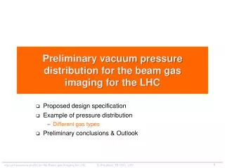
Preliminary vacuum pressure distribution for the beam gas imaging for the LHC Proposed design specification Example of pressure distribution Different gas types Preliminary conclusions & Outlook
Proposed design for the BGV for LHC From M. Ferro- Luzzi
Required densities • Densities (averaged over 1m) that would be needed for the BGV to work adequately for some representative gas types. Notes: since we only simulated H, O and Xe, we did this: * A and Fgoodfor CO2approximated by O3 #Fgoodfor Ne assumed same as for O (should be slightly better) • Can estimate performance of any other gas by estimating the Fgoodfrom the gas with the closest A and by scaling the density with A2/3(larger A, smaller density needed). • Reminder 1: is the molecular density, while the rate scales with the number of nuclei per cm3! • Reminder 2: what really counts is the target thickness (integrated along the useful z range) From M. Ferro- Luzzi
Example of a Possible Vacuum Layout Case of the BGV installed in 1 beam pipe For integration reasons the total length of the installed system is fixed to 7 m 8 cm NEG Coating 8 cm NEG Coating 2 x NEG Cartridges 0.5 m 1 m 0.25 m 2 m 1.25 m Standard vacuum chamber Conical transition 8 cm 4 cm NEG Coating 4 cm + NEG Coating Reduced aperture Gas Injection 7 m
Preliminary results and outlook • Investigation of favorable case • Limitation due to long term injection must be investigated • Implies BGV performance reduction • Implies possible LHC performance reduction (lifetime, vacuum instability, radiation …) • Reduced diameter aperture of 4 cm must be validation by optics team