Download
1 / 26
280 likes | 478 Views
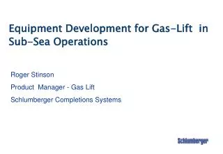
Equipment Development for Gas-Lift in Sub-Sea Operations. Roger Stinson Product Manager - Gas Lift Schlumberger Completions Systems. Deepwater Gas-Lift Challenges. Limited & costly intervention opportunities requires highly reliable equipment operational flexibility

E N D
Equipment Development for Gas-Lift in Sub-Sea Operations Roger Stinson Product Manager - Gas Lift Schlumberger Completions Systems
Deepwater Gas-Lift Challenges • Limited & costly intervention opportunities • requires highly reliable equipment • operational flexibility • Higher gas injection pressures • 3000 psi to 5000 psi • evaluate current products
Current Projects • RIPC Gas Lift Valve • normally open gas lift valve • 3000 PSI Gas Lift Valve • evaluate current products • development • Surface Controlled Downhole Flow Control • WRFC-H -Hydraulically Controlled • WRFC-E - Electrically Controlled
RIPC Gas Lift Valve Application • Developed for applications which will use two levels of injection pressure. • One point of injection for low operation injection pressure and one point of injection for high operation injection pressure • Use of this valve requires a low injection pressure for lifting from a shallow depth • A switch to a high pressure system to accommodate a deeper injection point will close the valve
Open Closed
Open Closed
1-1/2” IPO Gas Lift Valve - 3,000 PSI TRO • Currently have 3 existing 1-1/2” IPO Gas Lift Valve Designs • Limited to 1,700 PSI Dome Pressure • Test R-20, SR-20 & N-17R @ High Pressure To Determine Limitations • Analyze Test Results • Make Design Modifications For 3,000 PSI WP • Manufacture Final Design Prototypes • Test Final Design • Flow Test Final Design
Scope of Project To develop a gas lift valve capable of greater setting pressures (up to 3000 psi desired) for higher pressure injection systems in sub-sea completions. Testing to include: Phase I - Probe Testing - Cycle Testing Phase II - Probe Testing - Cycle Testing - Gas Flow Testing
Probe Testing Probe Testing measures the amount of stem travel the valve achieves per psi of pressure. Dome Pressures: 1000, 1500, 2000, 2500, 3000
Cycle Testing Cycle Testing measures the fatigue life of the bellows. Pressure is applied through the ports and across the bottom of the ball. One full cycle occurs upon opening and full closure.
Cycle Testing - Results • Valve set to 3000 psi Dome charge • results for all valves were unacceptable • N-17R Slightly better than R-20 • Valve set to 1500 psi Dome charge • mixed results • R-20 Considerably better than 3000 psi test • N-17R No significant improvement over 3000 psi test • Test ringed bellows and alternate material • Ringed bellows results comparable to no-ringed bellows • Alternate material improved cycling-higher load rate
Current Status • Development valve - alternate bellows material • Test additional alternate bellows designs &configurations • load rates • cycle testing • Future development decisions based on ongoing evaluation
WRFC - Wireline Retrievable Flow Control • Variable Orifice Gas Lift Valve • Side Pocket Mandrel Mounted • Wireline Retrievable • Electric or Hydraulic Operation • Same Operating System for Electric • Permanent Down Hole Gauge
Wireline Retrievable Flow Control Hydraulic (WRFC-H) Description Side pocket mounted hydraulically actuated Flow Controller that is remotely controlled from surface. Designed for flow rates up to 10,000 BBL/D, 30MMSCF/D. Features • Gas Lift and SCSSV based technology • Retrievable Valve for repair or replacement • Actuated through a single 1/4” control line • Customizable 6 position actuator Status 8 successful installations per August 2000
Wireline Retrievable Flow Control Electric(WRFC-E) Description • Electrically actuated • Retrievable Flow Control Valve Features • Based on Gas Lift technology • Retrievable valve for repair or • replacement • Actuated through a single 1/4” • tubing encased electrical • conductor line • Infinite position actuator • Annular and tubing pressures Status Field Test Q-1 2001
Sapphire Gauges Electronics Cartridge Bottom cross-section view Actuator Retrievable Flow Control Valve
ElectricHydraulic Max temp: 150 C 200 C Pressure rating: 5/10K PSI 5/10K PSI Flow area (see note): 0.75 in2 0.75 in2 Instrumentation Annular & tubing Separate Pressure & Temp Control resolution: Infinite Increments Note - Equivalent flow area WRFC Specifications
Norsk Hydro, TOGP • 30/40 Subsea installations planned • Control gas from gas cap to lift • Longer producing life • Eliminates compression facilities Safety Valve WRFC-H - used to control gas Penetrations in Gas Cap Sand control completion in oil zone