Download
1 / 23
230 likes | 251 Views
This project focuses on implementing Ethernet mezzanine boards for OPERA detector sub-detectors with FPGA technology. It involves preliminary tests, design validation, and collaboration meetings. The goal is to enhance data acquisition efficiency.

E N D
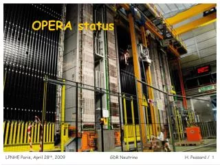
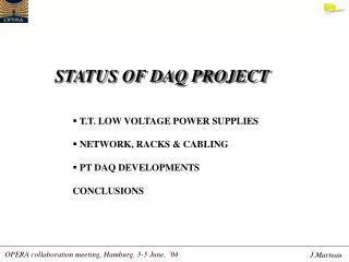
Status of the OPERA DAQ D.Autiero, J.Marteau T.Descombes informatics S.Gardien, C.Girerd, C.Guérin electronics
Ethernet mezzanine • Ethernet mezzanine: • Common part to all sub-detectors (TT, RPC, PT) : the mezzanine is simply plugged on the digital boards (regardless of the standard used : VME for RPC & PT, dedicated board for the TT). • Implementation: FPGA (readout sequencer), FIFO (temporary storage), m-processor (with Ethernet transceiver): MCM ETRAX from AXIS with imbedded LINUX. • Dimensions: 60mm60mm, 120 pins for external connections. • 3 boards in Lyon. To be done: • Preliminary tests (electrical, communication protocols, I/O) to validate the prototype : a dedicated test card is produced locally in Lyon for that purpose. • The up-to-date design has been circulated to the Naples group (RPC). • Organization of a dedicated meeting in Lyon with RPC & PT representative for the Ethernet mezzanine implementation.
6 cm 1 120 2 119 ……………… ……………… ……………… ……………… ……………… ……………… ……………… ……………… ……………… ……………… ……………… ……………… ……………… ……………… ……………… ……………… ……………… ……………… FPGA EP20KEFC324 EPC2 120 pins ( 4 x 30 ) 1.27 pitch ……………………. ……………………. ……………………. ……………………. …. …. …. …. …. …. …. …. …. …. …. …. …. …. …. …. …. …. …. …. …. …. …. …. …. …. …. …. …. …. …. …. …. …. …. …. …. …. …. …. …. …. ……………………. ……………………. ……………………. ……………………. 6 cm MCM IDT72V39110L10 61 62 59 60 Ethernet mezzanine
TT digital board • This board is directly plugged at the output of the analog board (2 flat cables) • Its main components are: • 1 ADC (12 bits), • 1 Ethernet mezzanine (FPGA, FIFO, m-processor), • 1 clock receiver unit (EPLD), • 1 high voltage module (ISEG), • 1 LED pulser (from BERN). • Dimensions: 290mm 85mm (see next slide). • Connectors: 3 Ethernet RJ45 (2 for the clock, 1 for the signal), 1power supply ( 7V), 1 RS232 (for debug purposes). • Dedicated meeting at CERN with the BERN group to review all the components.To be done: • Check the mechanics (position of the 2 fixation legs, isolating foam…). • Freeze the design a.s.a.p. (tight schedule for the production : deadline January 2004). • Produce 1st prototype for the summer (complete R/O chain from PM to DAQ).
TT digital board Analog board Ethernet mezzanine HV module LED pulser Clock EPLD RJ45 conn. We did not implement the Ethernet repeater in this 1st prototype (cost, # I/O) !!! we have 3 cables / digital board (clk, data, power supply)
TT digital board • Meeting @ CERN between Lyon & Bern : • Review of all the parts of the digital board : LAL chips signals, ethernet mezzanine,LED pulser, HV module, clk receiver (fine tuning before freezing the board layout) • Choice of all the components: ADC’s for charge R/O & for HV R/O, MUX, DAC’s, holddelay components • Definition of the register R/O convention • Review of all the signals & connectors from analog digital board • Discussion about the power supply : fuses ? monitoring ? cooling of the boards (temperature measurement with the 2nd ADC) ? • Milestones: test with analog board end of june (Bern also developping charge injector)
NIM outputs Ethernet transceiver (BFOOT) FPGA RJ45 Conn. ADC BFOOT board PPS signal ADC signal TA trigger EXT trigger
BFOOT board • Backup DAQ system for : TT modules tests at IReS & prototype tests : • Upgrade of a DAQ board designed for R&D purposes (tested with HPD’s & MaPMT’s) • Uses an Ethernet transceiver from Agilent (BFOOT) • Adapted to the VA-TA front-end electronics (no gain correction, possible individual thresholdsadjustment, dynamic range ~ 200 p.e.) • 5 boards received & tested : • 2 given to IReS group for the TT modules tests in Strasbourg • 2 will be used for tests (‘background measurements’ in Gran Sasso in june) • 1 spare • We received a connector that could permit to enclose the full electronics inside the TT end-cap(tests to be done soon).
Clock distribution system • General features : • A common clock is distributed from the GPS master card in the cavern to each node of OPERA : • GPS master card O/E converter : optical link • O/E converter master cards : M-LVDS bus (electrical link) • Master cards node cards (with ETRAX) : M-LVDS bus (electrical link) • The signal distribution is provided through M-LVDS bus • The system is bi-directional : the returned commands permit : • To acknowledge signals reception • To measure the propagation time in order to adjust delaysnode per node • Commands are encoded in the clock. The idea is to have a 2nd secured link from the global DAQ system to each individual node. The commands are : • FPGA RESET, • ETRAX REBOOT, • Time CYCLE INCREMENT (milli-PPS)
Clock distribution system Node card i SM2 SM1 MLVDS MLVDS O/E converter card Master card 0 « Slave » clock in Hall C (receives theGPS signal from the Outside antenna though a 8km optical fiber) 31 Master cards + 1 O/E converter card collected in 1 crate on the top of the detector (+3 additional master cards for the spectrometer)1 optical fiber from the « slave » card / SM Optical fiber Clock distribution system for TT (62 master cards, 992 nodes) PCI card
Clock distribution system Clock & R/O electronics implementation S.M. top view 11 boards RPC controller crate O/E converter 12 boards Power supply crates Master cards Ethernet switch PT controller crate 11 boards #0 #15 #0 #30 Optical fiber from slave card 16 nodes
Clock distribution system • Master & node cards : • Prototypes have been developped and successfully tested : • Communication protocols (tested with more than 20 meters cables between master & node) • Choice of serializer/deserializer components (Hotlink) • VHDL code (for the ALTERA EPLD) • The architecture of the node part has been frozen & implemented in the 1st version of the TT boards Prototype of master card Prototype of node card
Clock distribution system Master card VME format
Clock distribution system 100m optical fibre O/E converter Master card 10m ethernet cable 8 node cards 2m ethernet cable
Clock distribution system • Test of ½ TT plane (8 nodes) : • We test an (almost) complete R/O chain : 100m optical fibre O/E converter 2m ethernet cable master card 10m ethernet cable 1st node card 2m ethernet cable 2nd node card … • Test measurements : • Global propagation time measurement for the physical signal (~5ns / m) • Global propagation time including decoding (5 ms for the complete loop) • Individual node addressing (test of the M-LVDS bus) • Last step : interface this test bench with the PCI GPS card
Clock distribution system The O/E converter prototype
GPS distribution system • GPS PCI card architecture (« slave » card in Hall C): • Receives the GPS clock (we use a standard DATUM 637PCI antenna for tests). • Distributes the clock through optical fibres & receives signals from the different nodes (2 lines / SM, no optical splitter). • The idea is to design a new slave card using PCI standard with a “collaboration” from the ESAT company who designs the LNGS GPS system. • A visit to the ESAT company took place on March, 27th in Torino. We got many informations on software & hardware aspects: • Date pattern decoding • Readout ‘triggering’ • Oscillator choice • Sinus square signals conversion • VHDL code for signal reception • The 1st prototype of PCI board + O/E converter board is under completion.
GPS distribution system Inputs from GPS receiver (pps, 10Mhz, analog Irig B, digital Irig B) Optional for Lab tests Optical fiber from the master clock O/E Converter 10Mhz 5.10E-11 OC-050 Vectron Int. Master clock date EPC2 Hot Link 923 Optical fiber to the O/E converter of SM1 & SM2 Data+clock mixed TX1 HFBR1116T PECL Local bus APEX 20KE TX2 HFBR1116T PLX 9080 Hot Link 933 RX1 HFBR2116T Optical fiber From the SM1 Optical fiber From the SM2 RX2 HFBR2116T EEPROM Propagation time measurement (optional) To the station
G.U.I. under JAVA Home page
G.U.I. under JAVA TT eventdisplay ofa 5 planesevent
G.U.I. under JAVA Zoom on theprevious event
G.U.I. under JAVA 3D view
ON-LINE software status • G.U.I. : • Inputs from the various sub-detectors WG (TT, RPC, PT) concerning • data taking & acquisition • calibration • event display • CORBA event building : • Inputs from RPC & TT WG for the data to be stored (L0 trigger) • Inputs from all sub-detectors & from the simulation WG for L1 trigger • At present : storage in a relational DB (post-GRES) adaptation to ORACLE ? • Interface with the ROOT developed software ? • Network : • Simulation of the data rate to measure data transfer time, treatment time on the workstation (sorting & filtering), storage time in the DB • Tests are limited to max. 5 ETRAX boards. • 10 PC’s (166 MHz PII) have been also used (~3 times more powerful than ETRAX) but the results are difficult to extrapolate.