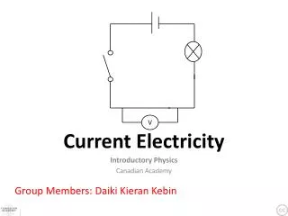
Current Electricity
890 likes | 908 Views
Current Electricity. Electrical Circuits. Waterfalls and Circuits: More in common than you think. Electrical Circuits can be thought of as a waterfall Voltage ( V ) Height of Waterfall Measured in volts (V) Current ( I ) Amount of water falling at one point at any moment

Current Electricity
E N D
Presentation Transcript
Waterfalls and Circuits:More in common than you think • Electrical Circuits can be thought of as a waterfall • Voltage (V) • Height of Waterfall • Measured in volts (V) • Current (I) • Amount of water falling at one point at any moment • Measured in amperes (A) • Resistance (R) • Constriction of water • Measured in ohms ()
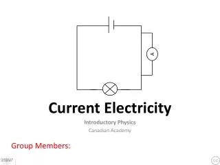
Simple Electric Circuit • Voltage (V) • Battery of the system • Measured in volts • Current (I) • Component using Electricity • Measured in amperes • Resistance (R) • Device inhibiting the flow of • electrons • Measured in ohms
Current • Current is a flow of charge (the charge is usually electrons) flows from positive to negative • The unit of current is the amp (the symbol for the amp is A). • The symbol for current is I. • Current is measured with an ammeter or multimeter.
For current to flow we need two things: • 1. There has to be a complete circuit. • 2. There has to be a source of potential difference (power supplies and batteries both act as a source of potential difference).
Potential difference (commonly called ‘voltage’) • Current will flow between two points if there is a potential difference between the two points. • This is a bit like saying that water will flow between two points if there is a height difference between the two points. • In an electric circuit current flows from the positive end of the battery to the negative end. • The positive end is represented with a long solid line, and the negative end is represented with a short solid line
Another way of thinking about potential difference is that it provides the ‘push’ to move the electrons around a circuit. • The unit of potential difference is the volt (the symbol for the volt is V) • The symbol for potential difference is V. • Potential difference is measured with a voltmeter or multimeter.
Resistance • Resistance opposes the movement of electrons around a circuit. • The unit of resistance is the ohm (the symbol for the ohm is Ω). • The symbol for resistance is R. • Resistance is measured with an ohmmeter or mulitmeter.
Making circuits • Requires a full complete “circuit” • Requires a potential difference (Voltage) • Requires a resister to reduce the flow of current in a circuit • Remember current flows from + to – • Always double check circuit before turning circuit on.
Electrical Circuits • An electric current is a flow of electric charge • Conductors are substances which allow current to flow through them freely • Conductors conduct electrical current very easily because of their free electrons. Most metals are good conductors of electrical current.
Electrical Circuits • Insulators are substances which do not allow electrical current to flow through them.
Exp: To test electrical conduction in a variety of materials, and classify each material as a conductor or insulator. Method: 1. Set up the apparatus as shown in the diagram. 2. Place the substance you want to test between the clips and see if the bulb lights. 3. Repeat with different substances and draw up a table of conductors and insulators. Result: Conclusion: If the bulb lights the material is a conductor. If the material does not light the material is an insulator. Some materials are better conductors that others.
How do we test for V, I, and Rin a Simple Circuit? • Device: • Digital Multimeter • Mathematically: • Ohm’s Law • Very Important Rule
Ohm’s Law • V = Voltage • I = Current • R = Resistance • To solve for V • V = I • R • To solve for I • I = V / R • To solve for R • R = V / I
Exp: Set up a simple circuit, use appropriate instruments to measure current, potential difference (voltage) and resistance, and establish the relationship between them. Method: 1. Set up the apparatus as shown in the diagram. 2. Read the current from the ammeter. • Read the voltage from the voltmeter. • Now connect an ohmmeter from A to B and read the resistance. • Adjust the variable resistor to give a slightly larger current, note voltage and resistance now. • Repeat a number of times. Result: Conclusion: Current = Voltage Resistance This is know as Ohm’s Law.
18 3 Check Your Understanding • For each of the following pictures, determine what the following values are for when the light bulb is lit: • Voltage • Current • Resistance 18 V R = = 6 3A #1 http://jersey.uoregon.edu/vlab/Voltage/
36 3 54 3 72 3 #2 R = = 6 R = = 18 #3 R = = 24 #4
voltage current V I R resistance = • 1. A resistor has a voltage across it of 12 volts and a current through it of 2.5 amperes. • Calculate the resistance of the resistor. 12 = 2.5 = 4.8W
voltage current V I R resistance = • 2. A voltage of 6 volts is across a resistor where the current is 0.5 amperes. • What is the value of the resistor? 6 = 0.5 = 12W
voltage current V I R resistance = • 3. Calculate the resistance of a component when a voltage of 24 V causes a current of 0.1 amperes. 24 = 0.1 = 240W
voltage current V I R resistance = • 4. If a current of 2 amperes exists through a lamp when it has 12 volts across it, what is the resistance of the lamp? 12 = 2 = 6W
voltage current V I R resistance = • 5. A torch bulb is marked "6 V, 0.25 A". • Calculate the resistance of the bulb. 6 = 0.25 = 24W
voltage current V I R • 6. A resistor is placed in a circuit. The voltage across it and current through it are measured as 12 volts and 0.02 amperes. • The resistor is now removed from the circuit and an ohmmeter connected across it. • What is the reading on the ohmmeter? resistance = 12 = 0.02 = 600W
V V V 2V 3V 5V • 7. Find the values of the resistors in the circuit below. R1 R2 R3 0.25A V 2 V 5 R1 = = = 8W R3 = = = 20W I 0.25 I 0.25 V 3 R2 = = = 12W I 0.25
voltage resistance V I R • 8. A resistor of resistance 50 W is placed in a circuit. The voltage across it is measured as 12 volts. • What is the current in the resistor? current = 12 = 50 = 0.24A
voltage resistance V I R • 9. A 15 W resistor is connected to a 9.0 V battery. • What is the current in the resistor? current = 9 = 15 = 0.60A
V I R • 10. A 25 W resistor is connected to a battery. • The current in the resistor is 0.25 A. • What is the voltage of the battery? voltage = current x resistance = 0.25 x 25 = 6.25V
V I R • 11. A 480 W resistor is connected to a battery. • The current in the resistor is 26 mA. • What is the voltage of the battery? voltage = current x resistance = 0.026 x 480 = 12.48V
Electric Circuits A circuit is a path where a current can flow If the flow is to be continuous, there can be no gaps in the path A closed circuit is required for a current to flow If the circuit is broken it is called an open circuit
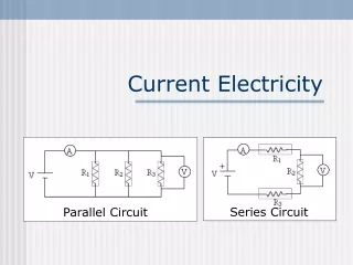
Electric Circuits There are two ways to connect multiple devices to a voltage source One is called series The other is called parallel Each has unique properties which we now examine
Series Circuit • A circuit that only has one path for current to flow through is called a series circuit.
Parallel Circuits • A type of circuit that has more than one path for current is called a parallel circuit.
If one part of the path is removed, the current continues to flow through the other paths of the circuit.
Series Circuits RTotal= R1+ R2+ R3
Series Circuits - A single pathway through the circuit - The current is the same everywhere in the circuit - Each device provides resistance and total resistance is the sum of the devices - Voltage divides among the devices
Series Circuit Calculation 10 ohm 20 ohm 30 ohm 12 Volt RTotal= R1+ R2+ R3
Parallel Circuits - Each device connects to the voltage source - Voltage is the same across each device - Current from source divides into devices - Total current is the sum of device currents - Current in each device is just V/R - Add devices, lower total resistance
In a series circuit: RTotal= R1+ R2+ R3
- Moving charges do work - We can heat the filament in a light bulb - We can turn the rotor in a motor - The rate at which work is done is power - Electric Power = current x voltage - Units are watts = joules/sec = amps x volts Electric Power
Electric Power Electric Power = current × voltage P = I × V