Lesson 15 Heat Exchangers
390 likes | 1.67k Views
Lesson 15 Heat Exchangers . DESCRIBE the difference in the temperature profiles for counter-flow and parallel flow heat exchangers. DESCRIBE the differences between regenerative and non-regenerative heat exchangers.

Lesson 15 Heat Exchangers
E N D
Presentation Transcript
Lesson 15Heat Exchangers • DESCRIBE the difference in the temperature profiles for counter-flow and parallel flow heat exchangers. • DESCRIBE the differences between regenerative and non-regenerative heat exchangers. • Given the temperature changes across a heat exchanger, CALCULATE the log mean temperature difference for the heat exchanger. • Given the formulas for calculating the conduction and convection heat transfer coefficients, CALCULATE the overall heat transfer coefficient of a system.
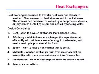
Heat Exchangers • Transfers thermal energy between fluids • Common applications include boilers, fan coolers, cooling water heat exchangers, and condensers. • Classifications • Ordinary heat exchanger • Single-phase • Both of the fluids (cooled and heated) remain in their initial gaseous or liquid states • Usually of the tube-and-shell type • Two-phase • Either of the fluids may change its phase during the heat exchange process • Includes steam generator and main condenser of nuclear facilities • Regenerators • Cooling towers
Heat Exchanger Components • Shell • Tubes • Relief Valves • Vacuum Breakers
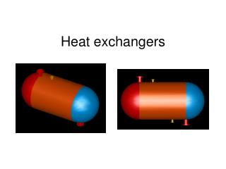
Parallel and Counter-Flow Designs • Heat exchangers modes of operation and effectiveness are largely determined by the direction of the fluid flow within the exchanger. • Most common arrangements for flow paths • Counter-flow - the direction of the flow of one of the working fluids is opposite to the direction to the flow of the other fluid • Parallel flow. - both fluids in the heat exchanger flow in the same direction • More heat is transferred in a counter-flow arrangement than in a parallel flow heat exchanger.
Parallel-flow Design • Advantageous when two fluids are required to be brought to nearly the same temperature. • Disadvantages • Large temperature difference at the ends causes large thermal stresses. • The temperature of the cold fluid exiting the heat exchanger never exceeds the lowest temperature of the hot fluid.
Counter-flow Design - Advantages • More uniform temperature difference between the two fluids minimizes the thermal stresses throughout the exchanger. • Outlet temperature of the cold fluid can approach the highest temperature of the hot fluid (the inlet temperature). • More uniform temperature difference produces a more uniform rate of heat transfer throughout the heat exchanger.
Parallel or Counter Flow • In both parallel or counter-flow, heat transfer within the heat exchanger involves both conduction and convection. • Process takes place over the entire length of the exchanger • Temperature of the fluids as they flow through the exchanger is not generally constant • Non- constant temperature causes variation in the rate of heat transfer along the length of the exchanger tubes
Non-Regenerative Heat Exchanger • Non-regenerative application is the most frequent heat exchanger application • Involves two separate fluids. • One fluid cools or heats the other with no interconnection between the two fluids. • Heat that is removed from the hotter fluid is usually rejected
Regenerative Heat Exchanger • Typically uses the fluid from a different area of the same system for both the hot and cold fluids. • The water returning to the primary system is pre-heated by the water entering the purification system. • Minimizes the thermal stress in the primary system piping due to the cold temperature of the purified coolant being returned to the primary system. • Reduces the temperature of the water entering the purification system prior to reaching the non-regenerative heat exchanger, allowing use of a smaller heat exchanger to achieve the desired temperature for purification. • Primary advantage of a regenerative heat exchanger application is conservation of system energy (that is, less loss of system energy due to the cooling of the fluid). • Can work in conjunction with non-regenerative heat exchanger Example : the purification system of a reactor facility. (see next slide)
Heat Exchanger Failure Mechanisms and Symptoms • Air Binding • Tube Leaks • Heat Transfer Reduction
Cooling Towers • Cools the water of a steam power plant • Steady-state process like the heat exchange in the ordinary heat exchanger. • Large chambers loosely filled with trays or similar wooden elements of construction. • Water to be cooled is: • pumped to the top of the tower • sprayed or distributed by wooden troughs. • falls through the tower, splashing down from deck to deck. • part of it evaporates into the air that passes through the tower. • Enthalpy needed for the evaporation is transferred to the air, • Air flow is either horizontal due to wind currents (cross flow) or vertically upward in counter-flow to the falling water.
Log Mean Temperature Difference Application To Heat Exchangers • To solve certain heat exchanger problems, a log mean temperature difference (LMTD or ΔTlm) must be evaluated before the heat removal from the heat exchanger is determined. • Example