Download
1 / 9
90 likes | 179 Views
Sensors for white line following car. Harry Byrne p133366. Team Layout. We decided to break the project up into three main areas. Fawaz Alanazi – Motor control Tom Baines – mincrocontroller Harry Byrne – Sensors and power supply. Sensors.

E N D
Sensors for white line following car Harry Byrne p133366
Team Layout • We decided to break the project up into three main areas. • FawazAlanazi – Motor control • Tom Baines – mincrocontroller • Harry Byrne – Sensors and power supply
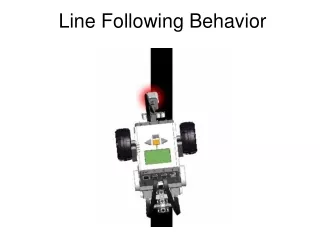
Sensors There are various options for sensors to follow a white line such as: • LEDs and photodiodes • IR LEDs and photodiodes • LDRs (photoresistors) • IR LED’s and phototransistors • CCD Camera
The HOA0708 reflective sensor consists of an infrared emitting diode and an NPN silicon phototransistor
Comparator 339AN • These dual comparators feature high gain, wide • bandwidth characteristics. This gives the device oscillation • tendencies if the outputs are capacitively coupled to the • inputs via stray capacitance. This oscillation manifests itself • during output transitions (VOL to VOH). To alleviate this • situation, input resistors <10 kW should be used. • The addition of positive feedback (<10 mV) is also • recommended. It is good design practice to ground all • unused pins. • Differential input voltages may be larger than supply • voltage without damaging the comparator’s inputs. Voltages • more negative than –0.3 V should not be used.
Sensor circuit design • From the specification sheet of the sensor I had to work out a few resistor values. • For the IR LED there was a 1.6v drop and it used 30mA so using ohms law R=V/I 3.4/30mA=113Ω but used a 120Ω resistor as that was available from stores. • For the Phototransitor using the same calculation as it was limited to 100 micro Amps 5/100μA=47kΩ which was used as it was in stores.