Download
1 / 42
420 likes | 503 Views
Understanding GFCIs. Developed by NEMA Ground Fault Personnel Protection Section (5PP). What Is to Be Covered?. Electrical shock - why have GFCIs How GFCI’s “Think” Proper installation of a GFCI Wiring Errors Grounded Neutral Detection Testing GFCIs. Electric Shock.

E N D
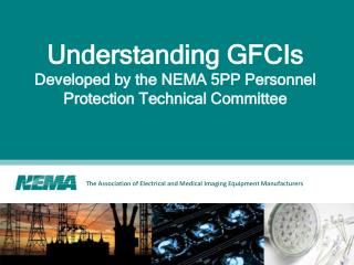
Understanding GFCIs Developed by NEMA Ground Fault Personnel Protection Section (5PP)
What Is to Be Covered? • Electrical shock - why have GFCIs • How GFCI’s “Think” • Proper installation of a GFCI • Wiring Errors • Grounded Neutral Detection • Testing GFCIs
Occurrences of Electrical Shock Deaths caused by electrical shock 25 Year Average (1960-1985) 102 - Street & Highway 120 - Farm 120 - Lightning 384 - Industry 474 - Home
Effects of Electric Shock 20 4 AMPERES AND OVER Heart Paralysis, Serious Tissue and Organ Burning 15 .050 AMPS TO 4 AMPS .1 - .2 Certain Ventricular Fibrillation .05 - .1 Possible Ventricular Fibrillation 10 4 .050 30 mA - Breathing Difficult, Fibrillation in small children 15 mA - Muscles “freeze” in 50% of the population >10 mA - Let-Go Threshold 5 mA - GFCI Trip Level 1 mA - Perception Level .030 .015 .010 .005 .001
Electric Shock Prevention System • Isolation (Physical) • Insulation • Double Insulation • Equipment Grounding • GFCI
Normal Circuit Operation 6A N Equipment L 6A Equipment Grounding Conductor (EGC)
Ground - Fault (Indirect Contact) 6A N L 12A EGC 5.940A Ground-Fault .060 A
Ground - Fault (Direct Contact) 5.90A N L 6A Ground-Fault .1 A
How GFCIs Think • Knowing how GFCIs “Think” will enable you to understand • why GFCIs must be installed a certain way • why GFCIs trip under various circumstances • how to logically explain what appears to be illogical tripping
The Current “Adding Machine” 6A L Load N 6A If the current out = current back, the CT shows no output.
Current Adding Machine 6A L 240V Load L 6A 6A L 120/240V Load N L 6A
Current Adding MachineUnder Ground Fault Conditions Ground- Fault Load 6A L N 5.9A .1A
The Device is really a DCCI not a GFCI • Don’t change the GFCI acronym… Change how you think about GFCIs • GFCIs are really “Differential Current Circuit Interrupters” not “Ground Fault circuit Interrupters” • Yes… they trip on ground fault caused differential current, but they also trip on other types of differential current as well.
What’s in the GFCI?(receptacle) Solid state circuitry with grounded neutral detection Push-to-test button 120V Trip Mechanism 15K resistor Load terminals L N EGC Receptacle face on receptacle type GFCIs Line Terminals
What’s in the GFCI?(circuit breaker) Solid state circuitry with grounded neutral detection Push-to-test button Trip Solenoid 15K resistor CB Trip Mechanism Line (breaker jaw) Load “Hot” Load Neutral Neutral (to panel neutral bar)
What’s in the GFCI?(Plug-in) Push-to-test button 120V Mechanical Latching Device 120V Relay 15K resistor Load “Hot” Load Neutral Equip.Ground
Standard 120 Volt Connection(GFCI Receptacle) 120/240Vac Source N L1 L2 Line Terminals Load Terminals N
The Adding Machine? 1A L 120V N 1A
Multi-Wire Circuits One leg of multi-wire circuit in use 120W bulb 1A 120V 1A 120V 0A Switch Open
Multi-Wire Circuits Both legs of multi-wire circuit in use 120W 1A 120W 120V 0A 120V 1A If what goes out…. Comes back.. The GFCI sees zero total current on the circuit.
T R T R GFCI Receptacle on Multi-Wire Circuits Ø N Ø Use two GFCI receptacles Junction Box Separate Neutrals GFCI Receptacles Downstream receptacles Downstream receptacles
This “Old House” Problem GFCI installed on one circuit 6A L1 N ? 6A L2 Second circuit installed and neutral “stolen” from a close-by circuit
Line and Load Reversal on Receptacles Push-to-test button Contacts Load terminals To Downstream Receptacles To Panelboard Line Terminals Receptacle face
GFCI Circuit Breaker Miswiring Current does not return through the sensor in the circuit breaker
Grounded Neutral Detection 6A L ? N Neutral grounded downstream EGC ? .30 A
UL GFCI Tests • Every GFCI must pass the following “in-line” manufacturing tests • no trip below 4mA (no load) • must trip at 6mA (no load) • no trip below 4mA (with load) • must trip at 6mA (with load) • must trip with 2 ohm grounded neutral • must trip within 25 ms with a 500 ohm fault • must trip with “test button” • must not trip with “noise” • calibration test at 102V • test button at 132V • 1500V hi-pot
GFCI Testers • Why are testers used? • verify operation of the GFCI • check protection of downstream receptacles • Will not test • proper GFCI operation • ALL types of improper installation • Dangerous on 2-wire circuits • Will test for some types of improper installation • line/load reversal • which outlets are protected by GFCI • reverse polarity • presence of the equipment ground
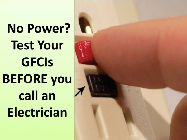
Push to Test Button • Test button indicates proper functioning of the GFCI • Does NOT indicate proper installation of the GFCI Push to test
Testing for Line/Load Reversal • Push the “reset” button on the receptacle • Plug a known “test load” into the GFCI receptacle • load could be a nightlight, GFCI tester, circuit tester, etc. • Push the “test” button (if GFCI trips - then the GFCI is properly functioning) • If the “test load” is energized, the GFCI receptacle is improperly installed
GFCI Testers Plug-in testers divert current to the equipment grounding conductor What if there is not equipment ground....? Such as in a 210-7(d)(3) application?
Summary • GFCIs have contributed to a reduction in the number of deaths due to electric shock • GFCIs look at the current going out and compare it to the current coming back • Avoid common wiring errors - “Think like the GFCI” • Remember that GFCIs detect grounded neutrals downstream - possible source of “nuisance tripping” • Test the GFCI by using the test button and a load