Download
1 / 21
210 likes | 332 Views
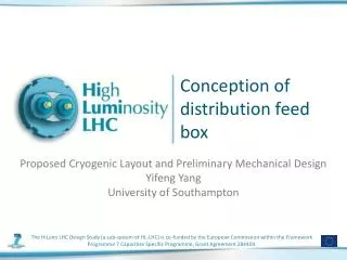
Conception of distribution feed box. Proposed Cryogenic Layout and Preliminary Mechanical Design Yifeng Yang University of Southampton. Main Activities in Task6.3. Designs: Concepts for distribution feed box (DFB) cryostat and interface to current leads

E N D
Conception of distribution feed box Proposed Cryogenic Layout and Preliminary Mechanical Design Yifeng Yang University of Southampton
Main Activities in Task6.3 • Designs: Concepts for distribution feed box (DFB) cryostat and interface to current leads • Concepts address the requirements for • maximum flow rate allowed • temperature margin • flow and heat transfer configurations • cable installation/spooling/support • mechanical considerations • Drawings at conceptual level for system and sufficient details for key components
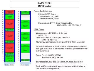
DFB Cryostat: Overall Considerations • First Iteration of the Design Concept • Two meetings (Dec 2011 and Mar 2012) at CERN for preliminary definition of the design goals and constraints • Modular Approach • DFB Cryostat module for connecting the superconducting cable/bus-bar (BB) to current leads (CL) • Current lead module • Connection module between BB and CL • BB splice and termination • HTS bridge cable between BB and CL • Heat exchanger and flow management for CL and HTS bridge
DFB Cryostat Module • Fully modular outer and inner vessels • Standard coupling between the modules • CF flanges for prototypes • Flexible inter-connection could be eventually integrated with the inner vessel module. • Welding possible for final design • Access to inner vessel for soldering HTS bridge BB or future repair/upgrade
DBF Cryostat Module: Vessels Assembly • Angled port for CL entry to inner vessel for HTS bridge • Reduced outer vessel diameter by insertion of the inner vessel at angle and rotation into final position (instead of raised from the base) • Radiation shield by contact to He gas lines
DFB Module: Bus-bar integration • Easy coupling to CryoFlexTM lines of the bus-bar • Common vacuum shared by the cryostat module and bus-bar CryoFlexTM lines • Continuation/distribution/addition of multiple He gas lines
Current Leads Module • Common vacuum with the cryostat module • Insulated cold envelope to the inner vessel of DFB • Assuming He cooling gas stream(s) injected from the cryostat module • ATS bridge made of a stack assembly of 2G YBCO tapes (e.g. 50-100 tapes for 20kA). The bridge has some flexibility in the direction perpendicular to the tapes’ broad face. • HTS bridge pre-soldered to CL (see below) • HTS linker pre-shaped for connection to BB splice termination (see below)
Current Leads Module: installation • Tilted insertion into the inner vessel to accommodate the pre-shaped HTS bridge
Connecting Current Lead to Bus-bar • Pre-spliced superconducting cable/bus-bar with prepared termination for soldering to HTS bridge
Connecting Current Lead to Bus-bar • Pre-spliced superconducting cable/bus-bar with a prepared termination for soldering to HTS bridge in-situ inside the inner vessel The angled entry of pre-shaped HTS bridge allows soldering to BB in the BB axis and reduce the size of the termination (for smaller port sizes in the inner vessel.
Tasks for the 2nd iteration leading to DFB prototype • Cryostat module • Definition of cooling options and number of GHe lines • Mechanical support and thermal insulation for inner vessel • Radiation shield design and mock-up • Size optimization/minimization according to cable/bus-bar specification • Drawings for prototypes
Task for the 2nd iteration leading to DFB prototype Present baseline for cooling options (from task 6.2) Control schemes only for indications of requirements, to be defined by task 6.2.
Task for the 2nd iteration leading to DFB prototype Possible variations from the baseline of task 6.2 Control schemes only for indications of requirements, to be defined by task 6.2.
Task for the 2nd iteration leading to DFB prototype Possible variations from the baseline of task 6.2 Control schemes only for indications of requirements, to be defined by task 6.2.
Task for the 2nd iteration leading to DFB prototype • Current lead module • Definition of cooling options including HTS/HEX transition and choice of GHe source(s) • Insulation of inner vessel tube from the CL/HEX • Mock-up for HTS bridge • Mock-up for HTS section and transition to HTS bridge • Design/optimize HEX for a prototype • Gantry for current lead installation into the cryostat
Tasks for the 2nd iteration leading to a DFB prototype • Connecting HTS bridge to BB • Mock-up for splice/termination. • Heat transfer design for the termination and HTS bridge • Flow distribution/integration with current leads cooling gas • Soldering of HTS bridge mock-up to termination mock-up. Integration with the heat transfer arrangement and gas distribution
Studies on the thermo-electrical performance of the cable/bus-bar and circuit models • 5m test rig ready and tested • Experimental work on the twisted pair cables with EuCARD • Modelling work to start after the magnet topology and cable specifications are defined • Some preliminary ideas of quench detection is being evaluated • To focus on local current sharing and contact resistances between the copper stabilization tapes and superconductors.
THEX TTop Tmid Tbot Example of quench characteristics of MgB2 twisted pair strand 20K, Quench from the middle by the heater 20K, Quench at the top due to temperature gradient V6 V5 V4 C3 C4 V3 V2 V1 Connected to current lead Heater-Insulation