Download
1 / 18
180 likes | 323 Views
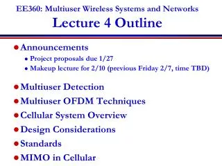
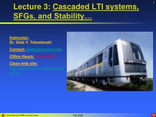
Lecture 3: Cascaded LTI systems, SFGs, and Stability…. Instructor: Dr. Gleb V. Tcheslavski Contact: gleb@ee.lamar.edu Office Hours: Room 2030 Class web site: http://ee.lamar.edu/gleb/dsp/index.htm. Cascaded LTI. y n. y n. v n. w n. x n. x n. (a). h 1,n.

E N D
Lecture 3: Cascaded LTI systems, SFGs, and Stability… Instructor: Dr. Gleb V. Tcheslavski Contact:gleb@ee.lamar.edu Office Hours:Room 2030 Class web site:http://ee.lamar.edu/gleb/dsp/index.htm
Cascaded LTI yn yn vn wn xn xn (a) h1,n h2,n h1,n h2,n (3.2.1) (3.2.2) According to (3.2.2), system (a) is equivalent to (b): (b) Note: this property is a result of linearity
+ + + + + + + + + + + + Fundamental direct forms of Signal Flow Graph (SFG) vn yn S3n S1n Fundamental Direct form SFG z-1 -a1 S2n S4n z-1 -a2 xn b0 h1,n h2,n z-1 … z-1 b1 xn wn yn xn wn yn z-1 b0 b0 b2 z-1 z-1 z-1 z-1 -a1 b1 b1 -a1 … wn-1 z-1 z-1 z-1 b2 b2 -a2 -a2 wn-2 z-1 z-1 … … z-1 … … h1,n h2,n Equivalent (Direct 2) form
SFG description for the Fundamental Direct form SFG (for SOS): Next state: (3.4.1) Output: (3.4.2) (3.4.2) Here {A,b,c,d} are state-space description. They represent one clock-cycle for a piece of soft/hard-ware.
SFG description (cont) A – the system matrix b – input matrix c – output matrix d – transmission matrix For the equivalent (Direct 2) form of SFG: (3.5.1) (3.5.3) (3.5.2) (3.5.4) (3.5.5) (3.5.6)
SFG description (cont 2) (3.6.1) (3.6.2) Holds only for n-1-l ≥ 0 (3.6.3) For the DF 2, the initial state depends on initial conditions but it’s NOT the same! Fundamental Direct form: {A, b, c, d} Direct 2 form: These systems are equivalent in terms of input/output!
SFG description (cont 3) For the DF2 (3.5.3): Q.: can we find S-3? It’s not trivial since we would need to know x-2 etc. However, we don’t really need it!
SFG relations Let’s say we need to find if is known… (3.8.1) (3.8.2) fundamental direct 2 (3.8.3) In our case, we only need two equations (n=0 and n=1) (3.8.4)
SFG and characteristic roots (3.9.1) (3.9.2) - eigenvalue (characteristic root) (3.9.3) (3.9.4) (3.9.1) (3.9.4) !!! (3.9.5)
Stability triangle for a causal BIBO system: (3.10.1) (3.10.2) (3.10.3) (3.10.4) (3.10.5) Stability triangle (3.10.6) Coefficients must be inside the triangle For systems of higher orders, there are no simple conditions – can always cascade!
Stability triangle The parabola a2 = a12/4 splits the stability triangle into two regions. The region below it corresponds to real and distinct roots 1, 2: Impulse response: (3.11.1) The points on the parabola result in real and equal (double) roots (poles) 1, 2: Impulse response: (3.11.2)
Stability triangle The points above the parabola (a12 < 4a2) correspond to complex-conjugate roots 1, 2: Assuming the roots (poles) in the form: (3.12.1) the filter coefficients are: (3.12.2) And the corresponding impulse response: (3.12.3) has a decaying oscillatory behavior.
More on SFG relations (3.13.1) (3.13.2) (3.13.3) (3.13.4) (3.13.5) Many systems are equivalent in terms of I/O, hn but are different inside! State space description is not unique in terms “what’s going inside”!
+ + + + Overflow control (3.14.1) Fixed-point representation may cause a state overflow! xn cs cs-1 b0 yn z-1 z-1 -a1 b1 Consider a second order system z-1 S1,n yn/ z-1 -a2 b2 S3,n S2,n S4,n (3.14.2) We cannot change the system - it’s given. Instead, we add a scaling coefficient csand cs-1 to compensate for it.
Overflow control (cont) Determinant of SFG: We may use the original hn to find the output find cs – experiment! cs does not change the determinant of SFG.
+ + + + Overflow control (cont 2) If we have a cascade… To make sure that the input of the 2nd cascade is bounded cs-1 xn cs cs(2) xn cs-1 csb0 yn We can also embed cs into b-coeffs z-1 z-1 -a1/2 csb1 2 z-1 z-1 -a2/2 csb2 Implementations: a2 1 a1 2 1 1 This way we add quantization noise! -1
+ + + + + Overflow control (cont 3) Alternative implementations: Drawbacks? 1st option: cs-1 xn 1/2 2 Add additional components to the system 2nd option: xn cs-1 csb0 yn z-1 z-1 -a1/2 csb1 z-1 -a1/2 csb2 z-1 It’s better to NOT divide a2 since it is less than 1 this way we don’t introduce quantization noise. We chose to divide by 2 since 2 is a minimum divider that bounds a1 to 1. -a2
Overflow… Assume we use 8 bits to represent integer numbers… obviously, from 0 to 255. If A = 255 and B is just 1… C = A + B = 256… which cannot be represented by 8 bits. As a result back