Download
1 / 86
860 likes | 963 Views
Universal Serial Bus Host Specification and Implementation. 304-648B: VLSI Design Atanu Chattopadhyay May 18, 2001. Section 1: The USB Protocol and Components. Introduction to the USB Protocol. External Bus Standard. Allows connection of peripheral devices.

E N D
Universal Serial Bus Host Specification and Implementation 304-648B: VLSI Design Atanu Chattopadhyay May 18, 2001
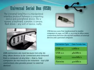
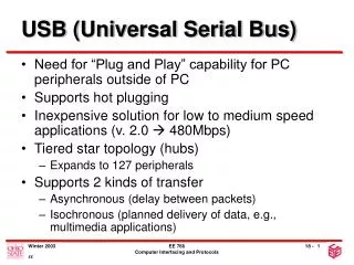
Introduction to the USB Protocol • External Bus Standard. • Allows connection of peripheral devices. • Connects Devices such as keyboards, mice, scanners, printers, joysticks, audio devices, disks. • Facilitates transfers of data at 480 (USB 2.0 only), 12 or 1.5 Mb/s (mega-bits/second). • Developed by a Special Interest Group including Intel, Microsoft, Compact, DEC, IBM, Northern Telecom and NEC originally in 1994
USB 2.0 • A USB 2.0 requires a similar engineering effort to USB 1.1 • Backwards and forwards compatible • Old devices work with new hosts • New devices work with old hosts • The only difference is really the addition of a 40x high-speed mode and the inclusion of a more complicated external bus interface
USB Speeds • Low-Speed: 10 – 100 kb/s • 1.5 Mb/s signaling bit rate • Full-Speed: 500 kb/s – 10 Mb/s • 12 Mb/s signaling bit rate • High-Speed: 400 Mb/s • 480 Mb/s signaling bit rate • NRZI with bit stuffing used • SYNC field present for every packet
Feature Set • Common protocol to interface various components and manufacturers. • Provides support for real-time data. • Allows Flexibility to send real-time (Isochronous/periodic) and non-real-time (Asynchronous) data over a common link. • Wide range of packet sizes • In High speed mode, a 1/8th of a 1 ms “microframe” can be specified to keep buffers small at high transfer rates
USB Connectors • There exist two pre-defined connectors in any USB system - Series “A” and Series “B” Connectors. • Series “A” cable: Connects USB devices to a hub port. • Series “B” cable: Connects detachable devices (hot-swappable).
Bus Hierarchy Main Memory Memory Bus CPU Bus CPU System Bus USB Internal Bus and interface USB Host Hub Host Computer External Device USB External Bus and interface USB Device
Host Root Hub Hub Hub Hub Functional Device Functional Device Functional Device Bus Topology • Connects computer to peripheral devices. • Ultimately intended to replace parallel and serial ports • Tiered Star Topology • All devices are linked to a common point referred to as the root hub. • Specification allows for up to 127 (27 -1) different devices. • Four wire cable serves as interconnect of system - power, ground and two differential signaling lines. • USB is a polled bus - all transactions are initiated by the host.
USB Host • Device that controls entire system usually a PC of some form. Processes data arriving to and from the USB port. • Contains a sophisticated set of software drivers. • Drivers schedule and compose USB transactions. • Access individual devices to obtain configuration information. • Software dependence of USB systems make it difficult to use on standalone systems without OS support • Physical interface to USB Root Hub is referred to as the USB Host Controller.
USB Hub • Tests for new devices and maintains status information of child devices. • Serve as repeaters, boosting strength of up and downstream signals. • Electrically isolates devices from one another - allowing an expanded number of devices. • Allows slower devices to be places on a faster branch. ie. allows a 1.5 Mb/s device may be connected to a 12 Mb/s line • Allows malfunctioning devices to be removed • May be integrated into various components or purchased as stand alone devices.
USB Devices • All functional devices are slaves - only responding to data reads or writes, never initiating any. • Many indicate a need to transmit or receive data through polling. • Contain registers that identify relevant configuration information. • Exist in conjunction with corresponding set of software drivers inside the host system. • Examples include joysticks, keyboards, printers, etc.
USB Software Interfaces Host System USB Device Client Software Function USB System Software USB Logical Device USB Host Controller USB Bus Interface
USB Software Interfaces • Client software determines what transactions are required with a given device. • What data is to be transferred? • Scheduling and configuration of data transfers is completed in USB system software level. • When and how often is data is to be transferred? • Data transfers are composed and regulated at the USB Host Controller level. • How is data to appear to the functional device? • How does system keep track of data that has been sent and received?
Frames, Transfers and Packets • Bandwidth is composed (by the host) into 1 ms time periods referred to as a frame. • Each frame is composed of a sequence of transactions that are to occur within the given time period. • Each transaction is composed of a sequence of packets that outline the format of and the corresponding data for each transaction. • A turn around time may exist between transfers of each respective packet. SOF Transfer n Transfer n+1 Portion of a Frame Packet 1 Packet 2 Packet 3
Frames, Transfers and Packets • Data is configured by the host system to be sent out within a given frame. • Length of frame can be dynamically altered by the host controller to facilitate more efficient use of bandwidth. • Impossible for the host to know exactly how long it will take to perform entire set of transactions at time of scheduling. • Start of Frame is indicated by a SOF packets. • Transactions are generally initiated with a token packet, followed by a data packet and concluded with a handshaking packet. • Lengthy transfers are broken into smaller ones and sent over a number of frames.
Transfer Types • There exists four basic types of transfers: • 1) Control Transfers • 2) Bulk Transfers • 3) Polling (Interrupt) • 4) Isochronous (real-time) Transfers • USB specification refers to Polling transfers as Interrupt Transfers. However, this terminology may be misleading and in this document we will use the term Polling Transfers.
Transaction Types • Control transfers are used in configuration transfers. • Assignment of endpoints and address fields. • Mandatory in all devices. • Control transfers are guaranteed 10% of bus bandwidth. • Setup stage of 8 bytes and data payload limited to 64 bytes. • Bulk transfers are used in non-real time transfers of large chunks of data. • Scanners, printers, digital cameras • Allows data transfers to be spread over a number of frames. • Use bandwidth remaining after all other transfers have been scheduled. • Data payload is limited to 64 bytes.
Transaction Types • Polling transfers are use to transfer small amounts of real-time data, such as a request to send data. • Chiefly used to poll interrupts, access devices such as mice and keyboards. • Scheduled to occur periodically. • Data payload limited to 64 bytes. • Isochronous transfers involve the movement of a large amount of real-time data and generally assume the greatest part of the USB bandwidth. • Digital telephones, speakers, CD-ROMs • Error detection and recovery is not supported. • Transfers are scheduled to occur every frame. • Data Payload limited to 1023 bytes.
0 7 8 14 15 19 20 24 PID ADDR ENDP CRC5 OUT, IN, Setup Packet Format 0 7 8 19 20 24 PID FRAME NUMBER CRC5 SOF Packet Format Packet Types • There are three basic types of packets: • Token- OUT, IN, SOF, Setup • Data - Data0, Data1 • Handshake - ACK, NAK, Stall • Token Packets • Use to establish parameters of a data transfer
0 7 8 N N+1 N + 17 PID DATA CRC16 Data0, Data1 Packet Format 0 7 PID ACK, NAK, Stall Packet Format Packet Types • Data Packets • Actual transfer of requested information • Two types of data packets - Data0 and Data1 are used to facilitate handshaking procedures (Alternating Bit Protocol) • Handshaking Packets • ACK - Data received without error • NAK - Device is temporarily unable to return/accept data • Stall - A catastrophic error has occurred
Field Types • PID - Packet Identifier • Indicates type of packet. • ADDR - Device Address • Indicates device being accesses • ENDP - Destination Endpoint • Indicates which set of registers within given device. • CRC5 and CRC16 - A Cyclic Redundancy Check field is affixed to end of packets to check for data errors • a 16 bit field is used for data, and a 5 bit field is used for all other packets • Frame Number - Identifies Frame Number • 11 bit field uniquely identifying the given frame • Data - Information to be transmitted • Must be an integral number of bytes.
USB Packet Encoding • Bit Ordering • Bits are sent onto the bus LSb first • SYNC fields • Appears on the bus as IDLE followed by the binary sequence “00000001” in the NRZI encoding • Packet Identifier Fields (PID)
USB Packet Encoding • Address Fields • 7-bit field, specifies source or destination of data packet • Endpoint Fields • 4-bit field, permits more flexible addressing of functions in which more than one endpoint is required • Frame Number Field • 11-bit field that is incremented by the host on a per-frame basis. • Rolls over upon reaching its maximum value of 0x7FFH
USB Packet Encoding • Data Fields • Ranges from 0 to 1023 bytes and must have an integral number of bytes. • Data bits within each byte are shifted out LSb first • End of Packet Fields • Both differential lines are driven to ‘0’ for two lock cycles and then one of them to ‘1’ for one clock cycle
USB Packet Encoding Idle Isochronous Transfers Bulk and Polling Transfers IN OUT Setup IN OUT Data0/1 NAK Stall Data0/1 Data0/1 Data0 Data0 ACK ACK NAK Stall ACK Control Transfers Idle Host Device
SYNC Packet 1 EOP idle SYNC Packet 2 EOP idle Transfer Formats • In order to maintain synchronization, a ‘0’ is inserted after every seven consecutive ‘1’s. • referred to as bit stuffing • A SYNC pattern, composed of seven ‘0’s and a ‘1’ is sent before every packet. • An EOP is use to signal the last bit of the packet has been sent. • The bus may is placed in an idle state while the device controlling the line is switched.
Alternating Bit Protocol • An alternating bit is attached to all data packets to aid in error detection. • A given data source initially sends a Data0 to a given sink. • If data transmission is successful (received and ACK) a Data1 is sent on the next transfer to the given sink. • If data transmission fails, the Data0 packet is sent again. • Used only with non-real time transfers. Data0 Data0 Tx (0) Rx 0->1 Tx (0) Rx 0->0 ACK ACK Tx 0->1 Rx (1) Tx 0->0 Rx (0) Successful Data Transmission Unsuccessful Data Transmission
Detected Errors • If an error is detected in the CRC field of any packet the corresponding transfer is terminated. • No handshaking packet is sent, and the line goes to idle. • If an error is detected, it indicates that the wrong device may have claimed the transaction and it is important that the transfer not be made for fear of corrupting data. • Host must recognize this situation and recover from it. • The alternating bit protocol provides a mechanism by which the source can re-transmit the same data and the sink can know this is old data and not an all-new transaction.
Differential Signaling • Serial data is transferred with the use of differential signals. • Data is NRZI (Non-Return to Zero, Inverted) encoded • A ‘1’ is indicated by the data maintaining a constant value and a ‘0’ is indicated by the data exhibiting a change in value • Allows the clock to be encoded with the data D+ D- 1 0 1 1 0 1 • Both D+ and D- are held to ‘0’ for 10 ms to indicate a reset. • Both D+ and D- are held to ‘0’ for 2 bit times to indicate an EOP.
Inter-Packet Delay • Definition • The time a device needs to wait to begin transmitting a packet after a packet has been received to prevent collisions on the USB. This time is based on the length and propagation delay characteristics of the cable and the location of the transmitting device in relation to other devices on the USB • Inter-Packet Delay is measured from the last transition in the EOP to the first transition that starts the next packet • A device is required to allow 2 bit times of inter-packet delay. The delay is measured at the responding device with a bit time defined in terms of the response. • The host must provide at least 2 bit times after last transition of the EOP and the start of the new packet
Inter-Packet Delay • If a device is expected to provide a response to a host transmission, the maximum inter-packet delay is 6.5 bit times • The maximum inter-packet delay for a host response is 7.5 bit times, measured from the host’s port pins • There is no maximum inter-packet delay between packets in unrelated transactions.
Bus Turn-Around Time • Definition • Neither the device nor the host will send an indication that a received packet had an error. Thus, absence of positive acknowledgement is considered to be the indication that there was an error. As a consequence of this method of error reporting, the host and USB function need to keep track of how much time has elapsed from when the transmitter completes sending a packet until it begins to receive a response. This time is called the bus turn-around time. • Both the device and the host require turn-around timers • The device bus turn-around is defined by the worst case round trip delay plus the maximum device response delay • If a response is not received within this worst case timeout, then the transmitter considers that the packet transmission has failed • USB devices timeout no sooner than 16 bit times and no later than 18 bit times after the end of the previous EOP
Bus Turn-Around Timer Usage Bus Turn-Around Time • If the host wishes to indicate an error condition via a timeout, it must wait at least 18 bit times before issuing the next token to ensure that all downstream devices have timed out
INPUT BIT bit 4 bit 3 bit 2 bit 1 bit 0 CRC Implementation • CRC-5 • Polynomial: G(X) = X^5+X^2+1
CRC Implementation • CRC-16 • Polynomial: G(X)=X^16+X^15+X^2+1 INPUT Bit 3 Bit 1 Bit 0 Bit 15 Bit 14 Bit 13 Bit 2
Frame List • USB system software compiles a linked list referred to as the Frame List detailing the data to be sent out during each frame. • Exact format of frame list and corresponding data structures is outlined by the OHCI (Open Host Controller Interface) or UHCI (Universal Host Controller Interface) standards. • Host controller accesses frame list to obtain a pointer to a data structure (referred to as a Transfer Descriptor) that outlines the details of the data to be sent. • Data structure contains a pointer to the data to be sent/ address to store incoming data. It also contains a pointer to the next data structure to be sent.
Frame List • Every millisecond the Host Controller Interface increases its Frame Number and accesses a subsequent address in the Frame List. • Real time data is accessed first by the host controller. • Non-real time data is queued and accessed when the host controller identifies that additional bandwidth is available. • The HCI updates (status/ data) each Transfer Descriptor that it processes.
Frame List Non-Real Time Data Transfer Descriptors Queue 1 Queue 2 Queue 3 Queue 3 Frame Pointer 1 Frame Pointer 2 TD TD TD TD TD Frame Pointer 3 TD TD Frame Pointer 4 TD TD TD Frame Pointer 5 Real Time Data Transfer Descriptors Frame List TD TD TD TD TD TD
Example • Assume that a given host has four USB ports and that all devices have been fully configured. • Attached to the four ports are a keyboard, a scanner and digital speakers with one port left open. • Three devices concurrently attempt to transfer data to and from the host machine. Keyboard • Each device requires a separate transfer type to communicate with the host system: polling, bulk and isochronous (i.e., real-time) respectively. Digital Speaker Unconnected Host Scanner
Example • Digital Speakers will require a constant influx of data whenever they are to be broadcasting a given signal. • The keyboard is to be checked every second frame to see if any new characters have been entered. • The scanner will use any available bandwidth to transfer various images to the host system. • USB system drivers will schedule the relevant transfers to occur as required by the functional devices.
Example Interrupt Transfers may or may not be sent, depending on system scheduling. Queue 1 Queue 2 Frame Pointer 1 Frame Pointer 2 Dig. Speak Keyboard Scanner Frame Pointer 3 Interrupt Transfer Descriptors to Keyboard Dig. Speak Frame Pointer 4 Scanner Real Time Data Transfer Descriptors to Digital Speakers Frame Pointer 5 Frame List Scanner Bulk Transfers will be added to the queue until all the available bandwidth has been used or there is no more data to transfer. Scanner Bulk Transfer Descriptors from Scanner Scanner
SOF Isochronous Transfer to Speakers Polling Transfer to Keyboard Bulk Transfer 1 to Scanner Bulk Transfer 2 to Scanner Example • The Host Controller will read the above linked list and compose the data in a format similar to that below: Multiple bulk transfers may be sent. Remember that bulk transfers are limited in size to 64 bytes and thus multiple transfers may be required.
Frame List Pointer • Composed of one word • Frame List Pointer [31:4] (FLP) - This field contains the address of the first data object to be processed in the frame and corresponds to memory address signals [31:4], respectively • Reserved [3:2] - These bits must be written as 0s • QH/TD Select [1] (Q) - 1=QH. 0=TD. This bit indicates to the hardware whether the item referenced by the link pointer is a TD or a QH. This allows the Host Controller to perform the proper type of processing on the item after it is fetched • Terminate [0] (T) - 1=Empty Frame (pointer is invalid). 0=Pointer is valid (points to a QH or TD). This bit indicates to the Host Controller whether the schedule for this frame has valid entries in it
Queue Headers (QH) 1/2 • Composed of 2 words • Fields of word #1 • Queue Head Link Pointer [31:4] (QHLP) - This field contains the address of the next data object to be processed in the horizontal list • Reserved [3:2] - These bits must be written as 0s • QH/TD Select [1] (Q) - 1=QH. 0=TD. This bit indicates to the hardware whether the item referenced by the link pointer is another TD or a QH. This allows the Host Controller to perform the proper type of processing on the item after it is fetched • Terminate [0] (T) - 1=Last QH (pointer is invalid). 0=Pointer is valid (points to a QH or TD). This bit indicates to the Host Controller that this is the last QH in the schedule. If there are active TDs in this queue, they are the last to be executed in this frame
Queue Headers (QH) 2/2 • Fields of word #2 • Queue Element Link Pointer [31:4] (QELP) - This field contains the address of the next TD or QH to be processed in this queue and corresponds to memory address signals [31:4], respectively • Reserved [3] - This bit must be 0 • Reserved[2] - This bit has no impact on operation. It may vary simply as a side effect of the Queue Element pointer update • QH/TD Select [1] (Q) - 1=QH. 0=TD. This bit indicates to the hardware whether the item referenced by the link pointer is another TD or a QH. This allows the Host Controller to do the proper type of processing on the item after it is fetched. For entries in a queue, this bit is typically set to 0 • Terminate [0] (T) - 1=Terminate (No valid queue entries). This bit indicates to the Host Controller that there are no valid TDs in this queue. When HCD has new queue entries it overwrites this value with a new TD pointer to the queue entry
Transfer Descriptor (TD) • Composed of 4 words • Important fields in word #1 • Link Pointer[31:4] (LP)- Fields pointing to another TD or QH • Depth/Breadth Select[2] (Vf) - 1 = Depth first, 0 = Breadth first This bit is only valid for queued TDs • QH/TD Select[1] (Q) - 1 = QH, 0 = TD Informs host controller whether item referenced to by LP is a QH or a TD • Terminate[0] (T) - 1 = LP field is valid, 0 = LP field is not valid
Transfer Descriptor (TD) • Important fields in word #2 • Isochronous Select[25] (ISO) - 1 = Isochronous Transfer Descriptor, 0 = Non isochronous transfer descriptor • Status bits • Active[23] - 1 = TD to be executed, 0 = TD shouldn’t be executed • Stalled[22] - 1 = STALL handshake was received from device • NAK received[19] - 1 = NAK received • CRC/Timeout error[18] - 1 = CRC or timeout error detected • Bitstuff error[17] - 1 = More than 6 ‘1’s in a row were detected • Actual Length[10:0] (ActLen) - Written by the host controller at the end of a Usb transaction to indicate the actual number of bytes that were transferred