Experiment 8: Diodes
560 likes | 793 Views
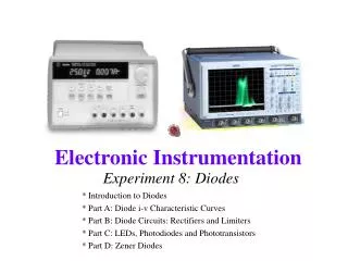
Experiment 8: Diodes. * Introduction to Diodes * Part A: Diode i-v Characteristic Curves * Part B: Diode Circuits: Rectifiers and Limiters * Part C: LEDs, Photodiodes and Phototransistors * Part D: Zener Diodes. Introduction to Diodes.

Experiment 8: Diodes
E N D
Presentation Transcript
Experiment 8: Diodes * Introduction to Diodes * Part A: Diode i-v Characteristic Curves * Part B: Diode Circuits: Rectifiers and Limiters * Part C: LEDs, Photodiodes and Phototransistors * Part D: Zener Diodes
Introduction to Diodes • A diode can be considered to be an electrical one-way valve. • They are made from a large variety of materials including silicon, germanium, gallium arsenide, silicon carbide …
Introduction to Diodes • In effect, diodes act like a flapper valve • Note: this is the simplest possible model of a diode
Introduction to Diodes • For the flapper valve, a small positive pressure is required to open. • Likewise, for a diode, a small positive voltage is required to turn it on. This voltage is like the voltage required to power some electrical device. It is used up turning the device on so the voltages at the two ends of the diode will differ. • The voltage required to turn on a diode is typically around 0.6 - 0.8 volt for a standard silicon diode and a few volts for a light emitting diode (LED)
Introduction to Diodes • 10 volt sinusoidal voltage source • Connect to a resistive load through a diode
Introduction to Diodes Only positive current flows
How Diodes Work At the junction, free electrons from the N-type material fill holes from the P-type material. This creates an insulating layer in the middle of the diode called the depletion zone.
How Diodes Work When the positive end of the battery is hooked up to the N-type layer and the negative end is hooked up to the P-type layer, free electrons collect on one end of the diode and holes collect on the other. The depletion zone gets bigger and no current flows.
Part A: Diode i-v Characteristic Curves • What is a i-v characteristic curve? • i-v curve of an ideal diode • i-v curve of a real diode
What is an i-v characteristic curve? • Recall that the i-v relationship for a resistor is given by Ohm’s Law: i=v/R • If we plot the voltage across the resistor vs. the current through the resistor, we obtain i The slope of the straight line is given by 1/R v
What is an i-v characteristic curve? If we change the axis variables in PSpice, we can obtain i-v characteristic curves.
i-v characteristic for an ideal diode iD Ideal Diode vD 0 When voltage across the diode is negative, the diode looks like an open circuit. When voltage across the diode is positive, the diode looks like a short.
i-v characteristic of a real diode • Real diode is close to ideal Ideal Diode
Real diode characteristics • A very large current can flow when the diode is forward biased. For power diodes, currents of a few amps can flow with bias voltages of 0.6 to 1.5V. Note that the textbook generally uses 0.6V as the standard value, but 0.7V is more typical for the devices we will use in class. • Reverse breakdown voltages can be as low as 50V and as large as 1000V. • Reverse saturation currents Isare typically 1nA or less.
The diode equation • The iD-vD relationship (without breakdown) can be written simply as: • vD is the voltage across the diode and iD is the current through the diode. n and Isare constants. VT is a voltage proportional to the temperature, we use 0.0259V. • Note that for vD less than zero, the exponential term vanishes and the current iD is roughly equal to minus the saturation current. • For vD greater than zero, the current increases exponentially.
Diode equation Both the simulated current vs. voltage (green) and the characteristic equation (red) for the diode are plotted. iD
Diode equation comparison • In this experiment, you are asked to find the parameters for the equation • That is, you need to find the constants in this equation so that it matches the data from an actual diode. Note that VT=25.9mV at room temperature, you need to find n and Is
Comparison • A good guess for the exact values of IS and n can be determined for a real diode by building the circuit and matching data from it to the diode equation in Excel. • Plot two series • series 1 : • series 2: calculate iD for 0<vD<1
Our Circuit • The IOBoard function generator can’t supply a large enough voltage for this experiment. • You will build a gain of 10 op-amp circuit and use it throughout the experiment. • Keep it together on your protoboard. • Disconnect the batteries when not in use. R2 is current sensing resistor D2 is diode to be measured Gain of 10 Op-Amp
Part B: Diode Circuits • Rectifiers • Voltage Limiters (Clippers)
Rectifiers • As noted above, the main purpose of diodes is to limit the flow of current to one direction. • Since current will flow in only one direction, even for a sinusoidal voltage source, all voltages across resistors will have the same sign. • Thus, a voltage which alternately takes positive and negative values is converted into a voltage that is either just positive or just negative.
A Half Wave Rectifier Since the diode only allows current in one direction, only the positive half of the voltage is preserved.
A Half Wave Rectifier • Note that the resulting voltage is only positive and a little smaller than the original voltage, since a small voltage (around 0.7V) is required to turn on the diode. 0.7V
Smoothing Capacitors • Filtering can be performed by adding a capacitor across the load resistor • Do you recognize this RC combination as a low pass filter? • You will see how this looks both with PSpice and experimentally
A Full Wave Rectifier The rectifier we have just seen is called a half-wave rectifier since it only uses half of the sinusoidal voltage. A full wave rectifier uses both the negative and positive voltages.
A Full Wave Rectifier • Note the path of current when source is positive. • What diodes does the current pass through when the source voltage is negative? In what direction does the current travel through the load resistor?
1.4V (2 diodes) A Full Wave Rectifier Note: Since a small voltage drop (around 0.7V) now occurs over two diodes in each direction, the voltage drop from a full wave rectifier is 1.4V.
Full Wave Rectifier With Smoothing Capacitor holds charge
Rectifiers and DC voltage • If a time-varying voltage is only positive or only negative all of the time, then it will have a DC offset, even if the original voltage had no offset. • Thus, by rectifying a sinusoidal signal and then filtering out the remaining time-varying signal with a smoothing capacitor, we obtain a DC voltage from an AC source.
Voltage Limitation • In many applications, we need to protect our circuits so that large voltages are not applied to their inputs • We can keep voltages below 0.7V by placing two diodes across the load
Voltage Limitation • When the source voltage is smaller than 0.7V, the voltage across the diodes will be equal to the source. • When the source voltage is larger than 0.7V, the voltage across the diodes will be 0.7V. • The sinusoidal source will be badly distorted into almost a square wave, but the voltage will not be allowed to exceed 0.7V. • You will observe this both with PSpice and experimentally.
Voltage Limitation • Case 1: The magnitude of the diode voltage is less than 0.7V (turn on voltage) Diodes act like open circuits
Voltage Limitation • Case 2: The magnitude of the diode voltage is greater than 0.7V (turn on D1) Diodes act like voltage sources
Voltage Limitation • Case 2: The current drawn by the diode is given by the resistor current
Input Protection Circuits • More than one diode can be connected in series to increase the range of permitted voltages
Part C: Diodes and Light • Light Emitting Diodes (LEDs) • Photodiodes and Phototransistors
Light Emitting Diodes • The Light-Emitting Diode (LED) is a semiconductor pn junction diode that emits visible light or near-infrared radiation when forward biased. • Visible LEDs emit relatively narrow bands of green, yellow, orange, or red light. Infrared LEDs emit in one of several bands just beyond red light.
Facts about LEDs • LEDs switch off and on rapidly, are very rugged and efficient, have a very long lifetime, and are easy to use. • They are current-dependent sources, and their light output intensity is directly proportional to the forward current through the LED. • Always operate an LED within its ratings to prevent irreversible damage. • Use a series resistor (Rs) to limit the current through the LED to a safe value. VLED is the LED voltage drop. It ranges from about 1.3V to about 3.6V. • ILED is the specified forward current. (Generally 20mA).
Photodiodes and Phototransistors • Photodiodes are designed to detect photons and can be used in circuits to sense light. • Phototransistors are photodiodes with some internal amplification. Note: Reverse current flows through the photodiode when it is sensing light. If photons excite carriers in a reverse-biased pn junction, a very small current proportional to the light intensity flows. The sensitivity depends on the wavelength of light.
Phototransistor Light Sensitivity The current through a phototransistor is directly proportional to the intensity of the incident light.
Part D: Zener Diodes • Zener diodes • i-v curve for a Zener diode • Zener diode voltage regulation
Zener Diodes • Up to this point, we have not taken full advantage of the reverse biased part of the diode characteristic.
Zener Diodes • For the 1N4148 diode, the breakdown voltage is very large. If we can build a different type of diode with this voltage in a useful range (a few volts to a few hundred volts), we can use such devices to regulate voltages. This type of diode is called a Zener diode because of how the device is made. • Zener diodes are rated according to where they break down. A diode with a Zener voltage (VZ) of 5V, will have a breakdown voltage of -5V.
i-v characteristic of Zener diodes Knee Current • For a real Zener diode, a finite current (called the knee current) is required to get into the region of voltage regulation • Just like regular diodes, Zener diodes have a small reverse saturation current in the reverse bias region and a forward bias threshold voltage of about 0.7V
Zener Diodes Circuits • Although Zener diodes break down at negative voltages, Zener voltages are given as positive and Zener diodes are typically placed in circuits pointing away from ground. • The voltage in this circuit at point B will • hold at VZ when the Zener diode is in the breakdown region. • hold at -0.7 when the Zener diode is forward biased • be equal to the source voltage when the Zener diode is off (in the reverse bias region).