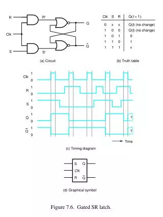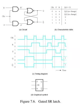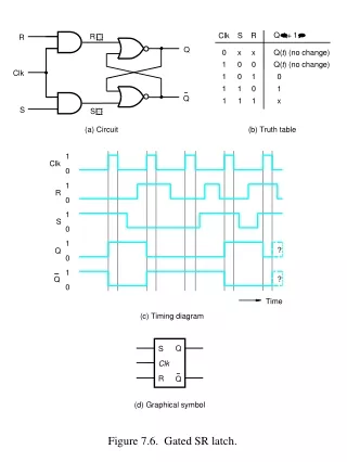
Gated or Clocked SR latch
380 likes | 2.03k Views
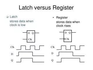
Gated or Clocked SR latch. Outputs change only when Enable(C) is HIGH. Master-Slave SR flip-flop. Clock signal. Positive edges. Negative edges. Edge-Triggered Flip-flops. Flip-flops : synchronous bistable devices

Gated or Clocked SR latch
E N D
Presentation Transcript
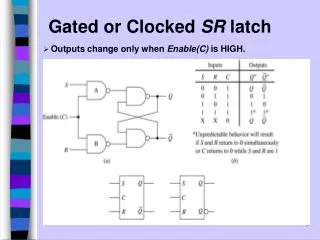
Gated or Clocked SR latch • Outputs change only when Enable(C) is HIGH.
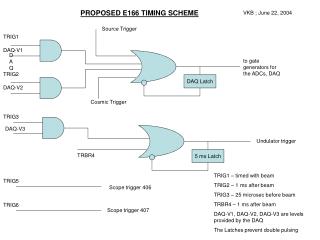
Clock signal Positive edges Negative edges Edge-Triggered Flip-flops • Flip-flops: synchronous bistable devices • Output changes state at a specified point on a triggering input called the clock. • Change state either at the positive edge (rising edge) or at the negative edge (falling edge) of the clock signal. Edge-Triggered Flip-flops
S C R J C K D C Q Q' Q Q' Q Q' S C R J C K D C Q Q' Q Q' Q Q' Edge-Triggered Flip-flops • S-R, D and J-K edge-triggered flip-flops. Note the “>” symbol at the clock input. Positive edge-triggered flip-flops Negative edge-triggered flip-flops Edge-Triggered Flip-flops
Positive Edge-Triggered Flip-flops • S-R flip-flop: on the triggering edge of the clock pulse, • S=HIGH (and R=LOW) a SET state • R=HIGH (and S=LOW) a RESET state • both inputs LOW a no change • both inputs HIGH a invalid • Characteristic table of positive edge-triggered S-R flip-flop: X = irrelevant (“don’t care”) = clock transition LOW to HIGH SR Flip-flop
NEGATIVE EDGE TRIGGERED R-S FLIP-FLOP Truth Table:
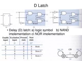
D S C R Q Q' CLK D Flip-flop • D flip-flop: single input D (data) • D=HIGH a SET state • D=LOW a RESET state • Q follows D at the clock edge. • Convert S-R flip-flop into a D flip-flop: add an inverter. = clock transition LOW to HIGH A positive edge-triggered D flip-flop formed with an S-R flip-flop. D Flip-flop
Q1 = X* D CLK D CLK D CLK Q Q' Q Q' Q Q' X Combinational logic circuit Y Q2 = Y* Z Q3 = Z* Transfer * After occurrence of negative-going transition D Flip-flop • Application: Parallel data transfer. To transfer logic-circuit outputs X, Y, Z to flip-flops Q1, Q2 and Q3 for storage. D Flip-flop
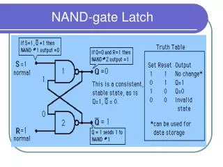
J-K(Jack–Kilby) Flip-flop • This simple JK flip-Flop is the most widely used of all the flip-flop designs and is considered to be a universal flip-flop circuit. • The basic gated SR NAND flip-flop suffers from two basic problems: number one, the S = 0 and R = 0 condition or S = R = 0 must always be avoided, and number two, if S or R change state while the enable input is high the correct latching action may not occur. • Then to overcome these two fundamental design problems with the SR flip-flop, the JK flip-Flop was developed. J-K Flip-Flop
J-K(Jack–Kilby) Flip-flop • The sequential operation of the JK flip-flop is exactly the same as for the previous SR flip-flop with the same "Set" and "Reset" inputs. • The difference this time is that the JK flip-flop has no invalid or forbidden input states of the SR Latch (when S and R are both 1). • The JK flip-flop is basically a gated SR flip-flop with the addition of a clock input circuitry that prevents the illegal or invalid output condition that can occur when both inputs S and R are equal to logic level "1". • Due to this additional clocked input, a JK flip-flop has four possible input combinations, "logic 1", "logic 0", "no change" and "toggle". J-K Flip-Flop
J-K Flip-flop • J-K flip-flop: Q and Q' are fed back to the pulse-steering NAND gates. • No invalid state. • Include a toggle state. • J=HIGH (and K=LOW) a SET state • K=HIGH (and J=LOW) a RESET state • both inputs LOW a no change • both inputs HIGH atoggle (Output changes state only once for each pulse) J-K Flip-Flop
J-K(Jack–Kilby) Flip-flop • Symbol and Circuit Diagram of JK Flip-flop: J-K Flip-Flop
J-K Flip-flop • Characteristic table. J-K Flip-flop
Master-Slave JK flip-flop A. Yaicharoen
T T J C K Q Q' Q Pulse transition detector CLK CLK Q' T Flip-flop • T flip-flop: single-input version of the J-K flip flop, formed by tying both inputs together. • Characteristic table. Q(t+1) = T.Q' + T'.Q T Flip-flop