Multicast on the LAN
570 likes | 664 Views
Learn about multicast addressing at Layer 2 and the Internet Group Management Protocol (IGMP) version 1, 2, and 3. Explore how routers and hosts communicate for efficient multicast group management.

Multicast on the LAN
E N D
Presentation Transcript
Multicast Addressing at Layer 2 • An IPv4 multicast address is 32 bits, of which the first 4 bits are always the same, leaving 28 bits. • A MAC multicast address is 48 bits, of which the first 24 bits are always the same (01-00-5E). One of the remaining bits is reserved, leaving 23 bits. • So, one multicast MAC address maps to 32 multicast IP addresses. • See Interdomain Multicast Routing, p. 18.
Ethernet Multicast Addressing IANA owns 01-00-5E vendor address block; half of it is assigned for IP multicast. 0 8 31 Class D address 32-bit IP address 1110 ignored, leaving 28 bits 48-bit Ethernet address 23 bits IEEE Ethernet multicast bit 0 24 47 0 000000010000000001011110 0 = Internet multicast 1 = Reserved for other use 00-00-00 thru 7F-FF-FF 01-00-5E-
Ethernet Multicast Addressing 233.255.1.255 IP Multicast Address 233 255 1 255 32 bits binary 23 bits binary 0 1 0 0 5 E 01:00:5e:7f:01:ff 48 bit Ethernet address
IGMP • Internet Group Management Protocol - how hosts tell routers about group membership • Routers also solicit group membership from directly connected hosts • RFC 1112 specifies version 1 of IGMP • Supported on Windows 95 • RFC 2236 specifies version 2 of IGMP • Supported on current Windows releases, and most UNIX systems • RFC 3376 specifies version 3 of IGMP • Provides source include-list capabilities (SSM!) • Included in Linux kernel 2.6 and later • Supported by Windows XP • Not supported by MacOS X
IGMPv2 • Router: • sends Membership Query messages to All Hosts (224.0.0.1) • default query-interval = 125 seconds • router with lowest IP address is Querier (rest non-queriers) • If lower-IP address query heard, back off to non-querier state • Other Querier Present Interval default: (robust-count x query-interval) + (0.5 x query-response-interval) = 255 seconds • listens for reports (whether querier or not) and adds group to membership list for that interface • default query-response-interval = 10 seconds • timeout (Group member interval) default: • (robust-count x query-interval) + (1 x query-response-interval) = 260 seconds • robust-count - provides fine-tuning to allow for expected packet loss on a subnet. Default = 2 (tunable from 2-10)
IGMPv2 • Host: • responds to router query with Membership Report messages to groups it is a member of (e.g.224.10.8.5) • waits 0-10 sec (default; specified in Query) • Hosts listen to other host reports • Only 1 host responds. Others become “idle-members.” • sends unsolicited Membership Reports (i.e., Join Messages) to group address (e.g. 224.10.8.5) • sends Leave messages to All Routers (224.0.0.2) • reports group membership ONLY – no sources. • Only the existence of local group members is known, not the actual members themselves (due to idle-member state).
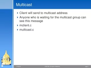
IGMP Protocol Flow - Join a Group I want to JOIN! 230.0.0.1 Router adds group I want 230.0.0.1 230.0.0.1 230.0.0.1 Forwards stream • Router triggers group membership request to PIM. • Hosts can send unsolicited Join membership messages – called reports in the RFC (usually more than 1) • Or hosts can join by responding to periodic query from router
IGMP Protocol Flow - Querier Yes, me! Still interested? (general query) 224.0.0.1 0-10 sec 230.0.0.1 I want 230.0.0.1 230.0.0.1 group 230.0.0.1 • Hosts respond to query to indicate (new or continued) interest in group(s) • only one host should respond per group • Hosts fall into idle-member state when same-group report heard. • After 260 sec with no response, router times out group. 125 sec 224.0.0.1
IGMP Protocol Flow - Leave a Group I want to leave! Anyone still want this group? 224.0.0.2 <230.0.0.1> 230.0.0.1 <230.0.0.1> I don’t want 230.0.0.1 anymore 1 sec (re-transmit timer) 230.0.0.1 <230.0.0.1> 230.0.0.1 group • Hosts that support IGMPv2 send Leave messages to all-routers group indicating group they’re leaving. • Router follows up with 2 group-specific query messages. • IGMPv1 hosts leave by not responding to queries (260 sec timeout).
Soft State • Say I set up an active multicast group, say by issuing a membership report. What happens if my computer goes down and never directly leaves the group? • This is fixed with “Soft State” • Everything has a timer, and if not periodically reinitiated the timer will expire and the state will be removed. • So there is no danger of some rogue group lasting forever.
H1 wants to receive from S = 1.1.1.1 but not from S = 2.2.2.2 With IGMPv3, specific sources can be included or excluded. In this case S = 1.1.1.1 is included. Video Server Video Server IGMPv3 Specified in RFC 3376 Enables hosts to listen only to a specified subset of the sources sending to the group Source = 1.1.1.1 Group = 232.1.1.1 Source = 2.2.2.2 Group = 232.1.1.1 R2 R1 R3 IGMPv3: MODE_IS_INCLUDE Join 1.1.1.1, 232.1.1.1 H1 - Member of 232.1.1.1
IGMPv3 Differences • Group-Source Report message is defined. Enables hosts to specify which senders it can receive data from. This maps directly to a PIM (S,G) Join for SSM. • Group-Source Leave message is defined. Enables host to specify the specific IP addresses of a (source,group) that it wishes to leave. • Other source filtering is supported, such as requesting traffic from all sources except those specified (blocking). This does not map directly to PIM (S,G) Join.
IGMPv3 Differences (cont’d) • Membership reports (Joins, Leaves) are sent to all IGMP listeners (224.0.0.22) instead of to <G>. • The idle-member state is eliminated. Hosts always send group membership reports to 224.0.0.22. • Membership report packet now can contain a list of group records including, for example, multiple group memberships. • Examples follow...
IGMPv2 Frame 2 (46 bytes on wire, 46 bytes captured) Ethernet II, Src: 00:00:86:51:bd:b2, Dst: 01:00:5e:05:06:07 Internet Protocol, Src Addr: 128.59.7.10 (128.59.7.10), Dst Addr: 224.5.6.7 (224.5.6.7) Internet Group Management Protocol IGMP Version: 2 Type: Membership Report (0x16) Max Response Time: 0.0 sec (0x00) Header checksum: 0x03f3 (correct) Multicast Address: 224.5.6.7 (224.5.6.7)
IGMPv3 Frame 10 (62 bytes on wire, 62 bytes captured) Ethernet II, Src: 00:00:86:51:bd:b2, Dst: 01:00:5e:00:00:16 Internet Protocol, Src Addr: 128.59.7.10 (128.59.7.10), Dst Addr: 224.0.0.22 (224.0.0.22) Internet Group Management Protocol IGMP Version: 3 Type: Membership Report (0x22) Header checksum: 0x0de3 (correct) Num Group Records: 2 Group Record : 224.5.6.8 Mode Is Exclude Group Record : 224.5.6.7 Mode Is Exclude
Switches and Snooping • IGMP host reports (Joins) tell the router to start sending multicast traffic to the LAN, since one or more hosts on the LAN are members of the group. • In a conventional shared broadcast LAN using switches that have no multicast smarts, the traffic is flooded to all hosts. • With multiple high bandwidth multicast sources (e.g. video at 5 Mbps), this does not scale. • There are a few techniques used to deal with this...
IGMP Snooping • Implemented by several vendors. Support for IGMPv2 is common; support for IGMPv3 is becoming more common. • What happens at the MAC layer: • IGMP snoopers add a bridge table entry for each multicast group destination address (GDA) to each switch port that has the interested member's unicast source address (USA) already on it. (Remember that there are likely to be hubs or switches downstream of a given switch port, so more than one USA can be on a single port.) • When an IGMP Leave is received, the GDA entries are pruned.
Why IGMP snooping isharder than it looks • The IGMP membership reports have to be captured from each host and suppressed to other hosts to prevent the others from going into idle-member state. Every interested host has to be spoofed into thinking it is the only member of the group, so that it actively sends membership reports. • The IGMP snooper then forwards one of these membership reports up to the router or makes up a fake membership report coming from one of: • the host • the switch’s management IP address, or • 0.0.0.0
Why IGMP snooping is harder than it looks, continued • Since multiple USAs can be on a port (via downstream switch), the switch has to actually do the IGMP membership query/timeout before pruning a port. • Since membership reports are sent to the same GDA as the (possibly high-bandwidth) multicast traffic, there is a potential for heavy loading of the switch CPU, unless you use more expensive ASICs that can separate the IGMP protocol messages from general traffic and route only the IGMP messages to the CPU. • The switch has to know which is the multicast router port. It does this by snooping for IGMP queries.
Join without IGMP snooping Switch 230.0.0.1 230.0.0.1 I want 230.0.0.1 230.0.0.1 230.0.0.1 230.0.0.1 230.0.0.1 I want 230.0.0.1 1. Host A sends membership report. 2. Switch floods it to all ports. 230.0.0.1 3. Router sends traffic (floods). 230.0.0.1 4. Host B wants to join. No IGMP message needed (idle-member).
Join with IGMP snooping Switch 230.0.0.1 230.0.0.1 I want 230.0.0.1 230.0.0.1 230.0.0.1 230.0.0.1 230.0.0.1 I want 230.0.0.1 1. Host A sends membership report. 2. Switch forwards it to router. 3. Router sends traffic. 4. Host B sends membership report. Switch suppresses it and adds port to bridge table.
Maintaining state w/IGMP snooping 224.0.0.1 ? Switch 230.0.0.1 230.0.0.1 224.0.0.1 General Query 224.0.0.1 ? 230.0.0.1 230.0.0.1 230.0.0.1 230.0.0.1 1. Router sends general query. 2. A&B both respond w/membership report (no idle member). 224.0.0.1 ? 3. Switch sends one to router and suppresses one.
Leave with IGMP snooping 224.0.0.22 <230.0.0.1> Switch 230.0.0.1 ? done 230.0.0.1 230.0.0.1 230.0.0.1 1. Host A sends Leave. 2. Switch spoofs G-specific query. 3. No reply, switch prunes port. (Nothing sent to router.)
Leave with IGMP snooping, cont’d Switch 224.0.0.22 <230.0.0.1> 224.0.0.22 <230.0.0.1> 230.0.0.1 ? 230.0.0.1 ? 230.0.0.1 ? 230.0.0.1 done 230.0.0.1 1. Host B sends Leave. 2. Switch spoofs G-specific query. 3. No reply; switch prunes port. 4. Switch sends Leave to router. 5. Router sends 2 G-specific queries, gets no response, and prunes the group. (Queries may [not] be suppressed)
Video Server Sourcing Multicast: conventional switch Switch 230.0.0.1 230.0.0.1 230.0.0.1 Multicast is just like broadcast: Flooded out all ports. 230.0.0.1
Video Server Sourcing with multicast-aware switch Switch 230.0.0.1 230.0.0.1 Multicast traffic is forwarded only to mrouter ports (learned by snooping for IGMP queriers). Exception: flood 224.0.0.0/24
CGMP • The proprietary Cisco Group Management Protocol puts the bulk of the Layer 3 logic in Layer 3 devices rather than cramming it into Layer 2 devices like IGMP snooping does. • The router sends CGMP Joins and Leaves to the switch, specifying the USA and GDA. • On receipt of an IGMP Membership Report, the router sends the switch a CGMP Join. • On receipt of an IGMP Leave, the router sends the switch a CGMP Leave. • IGMP membership reports still have to be suppressed so that hosts don't go into idle-member state.
CGMP, continued • CGMP does not work correctly with IGMPv3. • Leaves are not fully implemented, resulting in channel surfers causing a multicast flooding DoS on their subnet. • See http://www.cisco.com/univercd/cc/td/doc/product/software/ios122/122cgcr/fipr_c/ipcpt3/1cfmulti.htm#1046127. • Alan Crosswell notes that while CGMP is poorly documented, the hundreds of CGMP switches in his network at Columbia generally work pretty well for IGMPv2. • Newer switch models (running IOS rather than CatOS) seem to have abandoned CGMP.
PIM Snooping and RGMP • For Layer 2 networks with routers but no hosts (transit LANs). • PIM, not IGMP, is spoken among routers, so IGMP snooping does not work in this case. • PIM snooping and the Cisco-proprietary Router Group Management Protocol (RGMP) are used by the Layer 2 switch to send only the multicast flows that the router needs to the router's port. These work analogously to IGMP snooping (smarts in the switch) and CGMP (smarts in the router). • PIM snooping is still mostly experimental. Some Foundry Networks switches support it. • Cisco RGMP appears to only work for non-trunked interfaces (on Cat 6500 MSFC/2 IOS 12.1).
Problems with Multicast on the LAN • In general, multicast on the LAN is not as well understood as multicast on the WAN. • Switch behaviors are not standardized. But see RFC 4541, "Considerations for Internet Group Management Protocol (IGMP) and Multicast Listener Discovery (MLD) Snooping Switches", at http://www1.ietf.org/html.charters/magma-charter.html • Problems with switches: • when snooping is enabled and CPU load is high, they may drop packets that shouldn’t be dropped. • even without snooping, sometimes they step outside their bailiwick, trying to do non-Layer-2 tasks.
Observed problems w/snooping switches • See www.columbia.edu/~alan/igmp/ • Incomplete/nonexistent IGMPv3 implementations, including among vendors who claim IGMPv3 support. • Join works, Leave doesn’t, sometimes leading to flooding when the switch’s soft-state times out before the router’s. • Flooding of sourced (non-224.0.0.0/24) traffic to other switch ports. • Implementations vary across hardware/software versions of “same” vendor platform (e.g Catalyst 4500 Sup2 vs. Sup2+).
Case Study A few months ago I converted all our interfaces over to IGMP Version 3. Then I started getting complaints from our lab/classroom support group that Norton Ghost was failing for them. It would hang after about 3 minutes. So far the fix, without understanding why it works, has been to revert the interfaces to IGMP version 2. The switches downstream from these interfaces are running CGMP and CGMP LEAVE (which is actually a form of IGMP snooping/spoofing for IGMP Leaves sent to 224.0.0.2). I suspect that the fact that these switches are actually looking at IGMP packets may have something to do with the problem that reverting to v2 fixed... — Alan Crosswell
Case Study This author traveled to Los Alamos, New Mexico to help debug a multicast problem that had everyone stumped. Everyone was assuming the only known router on the subnet was also acting as the multicast gateway. Unfortunately, this wasn’t the case. A nominally Layer 2 switch on the subnet was accidentally configured with PIM active, and won the PIM Designated Router election. Of course, this Layer 2 switch had no upstream to anywhere. — Bill Nickless
More generally... • Switches and snooping may be evils, but they are necessary evils. Learn to cope with them. • www.cisco.com/warp/public/473/22.htmlis a good place to start.
PIM-SM Protocol Independent Multicast - Sparse Mode • The core multicast protocol: builds and tears down multicast trees. • Documented in RFC 4601 • “Protocol Independent” means independent of the protocol used to build the reachability table, not independent of IP. (More on reachability in a moment.) • “Sparse Mode” refers to the explicit join approach taken by PIM-SM — the protocol assumes that not everyone wants the data. • PIM also has a Dense Mode, which starts with the assumption that everyone does want the data. This is also known as a flood-and-prune approach. Not recommended. • Cisco offers a proprietary Sparse-Dense Mode, which is used for RP discovery.
Multicast Routing • Multicast routing can be thought of as the reverse of unicast forwarding. • Unicast forwarding is concerned with where the packet is going. • Multicast routing is concerned with where the packet will be coming from. • Multicast paths to receivers form a “tree”. The tree is built (or torn down) from the receiver back toward the source. This is easy to forget, but very important to remember.
Multicast Routing • PIM-SM uses an externally-provided reachability table to build forwarding topology. • The unicast forwarding table and the reachability table contain the same kind of information — unicast routes, or reachability information — and may in fact be the same table. (The point of having separate tables is to enable separate policies and paths for unicast forwarding and multicast routing. You need MBGP, IS-IS, or static mroutes to do this.)
Multicast Routing • Multicast forwarding topology is stored in outgoing interface lists (OILs). On each router, PIM-SM maintains an OIL for each group for which it has downstream listeners. Multicast packets received from a given source for a given group are sent out only on the interfaces specified in the appropriate OIL.
Multicast Routing • When a unicast packet shows up on a router interface, the destination address is looked up in the unicast forwarding table to determine where the router should send the packet next. • When a multicast (S,G) Join shows up on a router interface, the source address, S, is looked up in the reachability table to determine which of the router's interfaces offers the best way to reach S. This is called a reverse-path lookup. • The router adds the interface on which the (S,G) Join was received to the appropriate OIL, and sends an (S,G) Join to the next upstream router, as determined by the reverse-path lookup.
Multicast Routing • The process of doing reverse-path lookups, making OIL entries, and sending Joins continues hop-by-hop until it reaches a) a router that already has the necessary state, or b) the source's first-hop router. This process is called reverse-path forwarding (RPF); the reachability table is also called an RPF table. • Once the multicast distribution tree is built, multicast forwarding works similarly to unicast forwarding — but instead of using unicast forwarding tables to send packets out single interfaces, routers use OILs to send packets out multiple interfaces.
Multicast Distribution Trees • A shortest path tree (SPT) is a tree rooted in a multicast source. An SPT is sometimes called a source tree. • A rendezvous point tree (RPT) is a tree rooted in a multicast rendezvous point (RP). An RPT is sometimes called a shared tree.
Multicast Distribution Trees • In the original multicast service model, a connection between a source and a receiver is first set up by building an RPT from the receiver back to the RP, and an SPT from the RP back to the source. Once data starts flowing to the receiver, an SPT is built directly from the receiver back to the source.
Shortest Path Tree Source State Information: (S, G) S = Source G = Group Group Member 1 Group Member 2
RP Tree Shortest Path Trees Rendezvous Point Tree Source 1 Rendezvous Point Source 2 State Information: (*, G) * = Any Source G = Group Group Member 1 Group Member 2
Multicast Distribution Trees Compared • Shortest Path Tree • More resource-intensive; requires more state (of order n(S x G)) • You get optimal paths from source to all receivers, which minimizes delay • Best for one-to-many distribution • Rendezvous Point Tree • Uses less resources; requires less state (of order n(G)) • You may get suboptimal paths from source to all receivers, depending on topology • The RP itself and its location may affect performance • Best for many-to-many distribution • Necessary for in-band source discovery
ASM and SSM: Two ways to use PIM-SM • ASM: Any-Source Multicast. Traditional multicast – data and joins are forwarded to an RP. • All routers in a PIM domain must have RP mapping. • When load exceeds threshold, forwarding switches to an SPT. The default threshold is one packet; in this case, the sole purpose of the RPT is to learn which sources are active. (With IGMPv2, the receiver can only specify the group, not specific sources.) • State increases (not everywhere) as number of sources and number of groups increase. • SPT state is refreshed when data is forwarded and with Join/Prune control messages. • SSM: Source-Specific Multicast. PIM-SM without RPs – instead, the source is learned out-of-band, and the SPT is built directly to it.