Download
1 / 27
270 likes | 409 Views
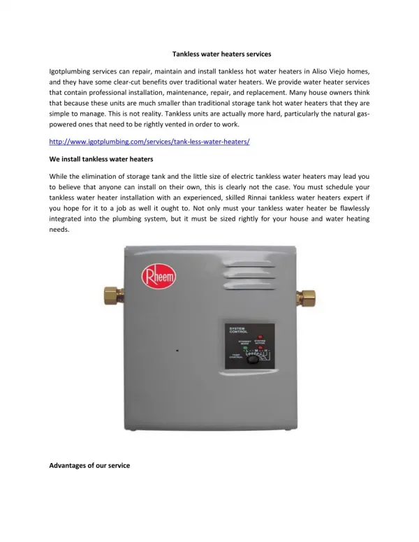
RELIABILITY ON DEMAND INTRODUCING A COMPLETE LINE OF TANKLESS GAS WATER HEATERS. American On-Demand Gas Water Heaters. A full product line of tankless water heaters by American. Utilized for Residential or Commercial applications. Interior and Exterior installation options.

E N D
RELIABILITY ON DEMAND INTRODUCING A COMPLETE LINE OF TANKLESS GAS WATER HEATERS
American On-Demand Gas Water Heaters • A full product line of tankless water heaters by American. • Utilized for Residential or Commercial applications. • Interior and Exterior installation options. • Natural Gas or Propane. • 16 different models covering a range of needs. 1
Rely on American • Benefit from the always reliable customer service of American and the comfort of endless hot water. • Combine the efficiency of the tankless technology with the expertise of the American brand. • Gain greater flexibility when it comes to controlling water temperature in the home. 2
On board diagnostics and safety monitoring Energy efficient, up to 84% thermal efficiency Continuous hot water up to 9.8 GPM (maximum flow rate) Direct electronic ignition; no pilot light Durable enough for 12-year limited warranty on heat exchanger and 5-year warranty on all parts Up to 237,000 maximum gas consumption Btu/h Natural gas or propane Reliable Technology 3
Inspired Comfort Standard Remote Controller Commercial Remote Controller • All models come with a Standard Remote Controller that can set the temperature within a specific range and can provide error codes to diagnose problems. • The Commercial Remote Controller can be used to achieve temperatures above 140ºF, up to 160ºF for the 305 models and up to 185ºF for the 505 and 705 models. 4
Remote Controller In Use Indicator Light Indicates hot water is being supplied (a tap is open) Temperature Display Shows the temp setting Priority Indicator Indicates that this controller is setting the temperature Error Codes When a fault is detected an error code flashes at the temperature setting Priority Button Priority can be changed to another controller if desired Thermostat Increases/decreases temp setting On/Off Button Will turn the water heater on/off 5
305 Model Specifications Interior Exterior • Model numbers: • Interior: GT-305-NI and GT-305-PI • Exterior: GT-305-NE and GT-305-PE • Btu/h Input: • Minimum 15,000/Maximum 199,000 • Flow rate: • Minimum 0.6 GPM/Maximum 5.3 GPM • Efficiency rating: • Interior 84%/Exterior 83% • Weight: • 50 lb. 7
505 Model Specifications Exterior Interior • Model numbers: • Interior: GT-505-NI and GT-505-PI • Exterior: GT-505-NE and GT-505-PE • Btu/h Input: • Minimum 15,000/Maximum 199,000 • Flow rate: • Minimum 0.6 GPM/Maximum 8.5 GPM • Efficiency rating: • Interior 84%/Exterior 83% • Weight: • 50 lb. 8
705 Model Specifications Exterior Interior • *Model number: • Interior: GT-705-NI and GT-705-PI • Exterior: GT-705-NE and GT-705-PE • Btu/h Input: • Minimum 19,000/Maximum 237,000 • Flow rate: • Minimum 0.6 GPM/Maximum 9.8 GPM • Efficiency rating: • Interior 84%/Exterior 83% • Weight: • 55 lb. *ASME models also available: Interior: AGT-705-NI and AGT-705-PI Exterior: AGT-705-NE and AGT-705-PE 9
Model Specifications Overview Approximate Model BTU Input Natural/Propane Hot Water Output (GPM) Shipping Number Minimum Maximum Maximum 45ºF Rise 77ºF Rise Weight (lbs.) GT-305-NI 15,000 199,000/190,000 5.3 5.3 4.2 50 lb. GT-505-NI 15,000 199,000/190,000 8.5 7.4/7.1 4.2 50 lb. GT-705-NI 19,000 237,000 9.8 8.8 5.1 55 lb. AGT-705-NI* 19,000 237,000 9.8 8.8 5.1 55 lb. GT-305-NE 15,000 199,000 5.3 5.3 4.2 50 lb. GT-505-NE 15,000 199,000 8.5 7.3 4.2 50 lb. GT-705-NE 19,000 237,000 9.8 8.7 5.1 55 lb. AGT-705-NE* 19,000 237,000 9.8 8.7 5.1 55 lb. *AGT-705-NI and AGT-705-NE models are ASME Certified. For Propane, change “N” to “P” in model number (e.g. GT-305-PI or GT-305-PE). INTERIOR MODELS EXTERIOR MODELS 10
Multi-System Options Number of Connected Water Heaters: Accessories Necessary: 2 (1) 2-Unit connection cable or (1) Multi-Unit connection kit 3 (1) Multi-Unit connection kit and (1) Multi-Unit connection cable 4 (1) Multi-Unit connection kit and (2) Multi-Unit connection cables 5 (1) Multi-Unit connection kit and (3) Multi-Unit connection cables • Connection cable or kits are available for multi-system integration. 11
Model Selection Guide • To properly size On-Demand units for a home, two factors are of critical importance . . . • Incoming ground water temperature - Will determine the amount of “temperature rise” required to achieve the desired hot water outlet temperature (120ºF is recommended) • Peak hot water demand - How much hot water the home will need during its busiest usage period 13
Peak Hot Water Demand • Consider all the applications and fixtures in the home that use hot water, including lavatory faucets, kitchen faucets, washing machines, dishwashers, showers and bathtubs. • Determine how many of these appliances and fixtures will be in use at the same time during the busiest usage period. • For example, if one kitchen faucet, one shower and a washing machine are all in use during the busiest period, use the number 3 to make your selection from the Model Selection Guide. 15
Model Selection Guide Ground Water Temperature Zone Appliances or fixtures in simultaneous use during peak demand Southern Zone Central Zone Northern Zone 1 305 or 505 305 or 505 305 or 505 2 305 or 505 305 or 505 305 or 505 3 505 or 705 (2) 505 or 705 (2) 505 4 (2) 505 (2) 505 (2) 505 5 (2) 505 (2) 705 (2) 705 6 or more Multi-system Multi-system Multi-system *Note: This Selection Guide is based on 120ºF outlet water temperature. 16
Dimensions – Interior Models 305/505 Models 705 Model 305/505 705 DIMDESCRIPTIONIn (mm)In (mm) A Width 14 (355.6) 18.5 (470) B Depth* 9.6 (244.5) 9.1 (230.5) C Height: Unit 22.9 (582) 23.6 (600) D Height: w/Brackets 25.5 (648.2) 25.2 (640) E Hot water outlet: from wall 3.6 (91) 4.3 (110) F Hot water outlet: from center 4.3 (110) 2.4 (61) G Cold water inlet: from wall 2.8 (70) 3.7 (94) H Cold water inlet: from center 1.1 (27) 2.0 (52) I Gas connection: from wall 4.3 (109) 2.2 (56.2) J Gas connection: from center 3.5 (89) 4.3 (110) K From base to gas connection 1.6 (40) 1.6 (40) From base to cold connection 2.0 (50) 2.0 (50) From base to hot connection 1.6 (41) 1.6 (41) *This is the minimum dimension from the wall. 20
Dimensions – Exterior Models 305/505 Models 705 Model 305 505 705 DIMDESCRIPTIONIn (mm)In (mm)In (mm) A Width 14 (355.6) 14 (355.6) 18.5 (470) B Depth 7.7 (196) 9.8 (249.5) 9.3 (236) C Height: Unit 19.8 (503) 22.9 (582) 23.6 (600) D Height: w/Brackets 22.5 (571) 25.4 (646.4) 25.2 (640) E Hot water outlet: from wall 3.4 (87) 3.8 (96) 4.5 (115) F Hot water outlet: from center 4.1 (105) 4.3 (110) 2.4 (61) G Cold water inlet: from wall 2.7 (68) 2.6 (75) 3.9 (99) H Cold water inlet: from center 0.4 (10) 1.1 (27) 2.0 (52) I Gas connection: from wall 3.0 (77) 4.1 (104) 2.4 (61.2) J Gas connection: from center 3.3 (83) 3.5 (89) 4.3 (110) K From base to gas connection 1.6 (40) 1.6 (40) 1.6 (40) From base to cold connection 2.0 (50) 2.0 (50) 2.0 (50) From base to hot connection 1.6 (41) 1.6 (41) 1.6 (41) 21
Pipe Sizing 22
Piping for Basic Installation On-Demand Water Heater 3/4″ Gas Connection KEY 3/4″ Ball Value Pressure Regulator 3/4″ Union Circulating Pump Check Value Bolier Drain Valve Pressure Relief Valve Solenoid Valve Gas Supply 3/4″ Hot Water Supply For Building Fixtures 3/4″ Cold Water Supply Equipment List: 1 Water Heater 1 Plumbing Installation Kit (Optional) 2 Unions 2 Ball Valves 2 Drain Valves 1 Pressure Relief Valve 23
Flue Terminal Clearances – Interior Models U.S. DIMDESCRIPTIONInstallations A Clearance above grade, veranda, porch, 12″ (30 cm) deck, or balcony B Clearance to window/door that may be open 12″ (30 cm) C Clearance to permanently closed window * D Vertical clearance to ventilated soffit, located * above terminal within horizontal distance of 2 ft. (61 cm) from center line of terminal E Clearance to unventilated soffit * F Clearance to outside corner * G Clearance to inside corner * H Clearance to each side of center line extended * above meter/regulator assembly I Clearance to service regulator vent outlet * J Clearance to non-mechanical air supply 12″ (30 cm) inlet to building or combustion air inlet to any other appliance K Clearance to a mechanical air supply 3′ (91 cm) above inlet if w/i 10 ft. (3 m) horizontally L Clearance above paved sidewalk/paved * driveway located on public property M Clearance under veranda, porch, deck, balcony * *For clearances not specified in ANSI Z223.1/NFPA 54 or CSA B149.1, clearances are in accordance with local installation codes and the requirements of the gas supplier. 24
Flue Terminal Clearances – Exterior Models U.S. DIMDESCRIPTIONInstallations A Clearance above grade, veranda, porch, 12″ (30 cm) deck, or balcony B Clearance to window/door that may be open 12″ (30 cm) C Clearance to permanently closed window * D Vertical clearance to ventilated soffit, located * above terminal within horizontal distance of 2 ft. (61 cm) from center line of terminal E Clearance to unventilated soffit * F Clearance to outside corner * G Clearance to inside corner * H Clearance to each side of center line extended * above meter/regulator assembly I Clearance to service regulator vent outlet * J Clearance to non-mechanical air supply 12″ (30 cm) inlet to building or combustion air inlet to any other appliance K Clearance to a mechanical air supply 3′ (91 cm) above inlet if w/i 10 ft. (3 m) horizontally L Clearance above paved sidewalk/paved * driveway located on public property M Clearance under veranda, porch, deck, balcony * *For clearances not specified in ANSI Z223.1/NFPA 54 or CSA B149.1, clearances are in accordance with local installation codes and the requirements of the gas supplier. 25
For more information visit www.americanwaterheater.com