Download
1 / 33
510 likes | 1.43k Views
MOLDED CASE CIRCUIT BREAKER BASICS. David Castor, P.E. History of MCCBs. 1904 - Cutter Manufacturing Co., Philadelphia , produces circuit breakers . They called it the Inverse Time Element breaker, or I-T-E breaker and the company later became the I-T-E Co.

E N D
MOLDED CASE CIRCUIT BREAKER BASICS David Castor, P.E.
History of MCCBs • 1904 - Cutter Manufacturing Co., Philadelphia, produces circuit breakers. They called it the Inverse Time Element breaker, or I-T-E breaker and the company later became the I-T-E Co. • 1925 - NEC- Circuit breakers required to be enclosed and externally operable. • 1932 - Westinghouse introduces their modern molded case air circuit breaker. • 1973 – First electronic trip unit
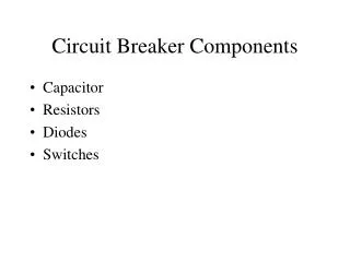
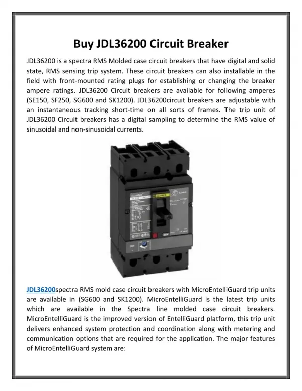
Basic MCCB Components • Molded Case • Line and Load Terminals • Operating Mechanism • Trip Bar • Contacts • Arc Extinguisher
Standards • In the US, the primary MCCB standard is UL 489. • UL 489 covers virtually all types of molded-case circuit breakers. • NEC and UL 489 requirements are generally harmonized and consistent • NEMA AB3 and AB4 are free standards on application and field inspection/testing of MCCBs.
Thermal-Magnetic MCCB • Electro-mechanical • Two separate tripping mechanisms: • Thermal inverse-time element for low level faults/overloading • Magnetic (Instantaneous) trip for short circuits • Magnetic trip may be adjustable
Thermal Element • Bimetallic Element • Unequal thermal expansion causes element to bend • Inverse time characteristics – higher current, more heat faster tripping. • Protects against long-term overloads, low current faults • Sensitive to ambient temperature
UL Requirements for Thermal Element • Must carry 100% of rated current continuously at 40 deg C ambient IN OPEN AIR. • At 200% rated current, maximum trip times are given based on breaker size:
Magnetic Trip • Electro-magnet in series with current. • Designed to trip above a certain current with no intentional delay. • Detects short circuit current • Adjustable in larger breaker sizes • Generally will respond to peak asymmetrical current • 1.5 cycle fault clearing or less • Magnetic trip is why arc-flash levels tend to be low when protected by MCCB. • MCCB must have instantaneous trip per UL489. • Can create mis-coordination for MCCBs in series
Typical Thermal-Magnetic TCC Thermal Magnetic
“Generic” MCCBs in EasyPower • Provide typical thermal-magnetic TCCs for MCCBs up through 1200 A. • TCCs consistent with UL 489 tripping requirements and IEEE 1584. • Use in design phase or when exact breaker type is not known. • Should be conservative • A “Generic” design sheet is also provided in Auto Design.
Motor Circuit Protectors (MCPs) • MCCB with NO THERMAL element. • “Magnetic-only” • Can ONLY be used as part of a listed combination motor starter. Overload relay provides the thermal protection • Cannot use as a feeder breaker. • In EasyPower treated as “thermal-magnetic”
Advantages of MCPs • Special application allows wider range of sizes and trip adjustments than standard thermal-magnetic breakers • Specially-designed trip coils with some transient suppression • Faster tripping for typical motor faults than fuses.
Solid-State Trip Units • Electronic (now all digital) current sensing replaces thermal and magnetic trip elements. • Trip mechanism and arc-extinguishing same as thermal-magnetic • More accurate and more flexible settings • Instantaneous still required. • Ground fault easy to provide • Becoming standard for larger size breakers • Required for 100%-rated breakers.
Typical TCC for Large MCCB w/SS Trip • Long-time pickup (may be fixed w/rating plug • Long-time delay • Short-time trip • Instantaneous trip • Ground trip • Metering functions • Communications Long-Time Short Time Instant.
MCCB Maintenance & Testing • Can be difficult to tell when MCCB needs replacing. • No user serviceable parts – opening case voids warranty. • Thermography has proven useful to get some assessment of breaker condition. • UL489 type testing requires two fault interruptions at the breaker max fault rating. • IEEE 1458 covers life expectancy and field testing of MCCBs. (Not free!) • Arc-Flash calculations assume all breakers will function within published TCC.
NEMA AB4 Covers MCCB Field Inspection and PM • Free standard • Replace not Repair
MCCB Interrupting Ratings • MCCB have a single short circuit rating, stated in rms symmetrical amps using ½ cycle network. • However, breaker testing is done at a specific power factor. If your system’s X/R exceeds the test value, the breaker must be de-rated. • This is done automatically using SmartDuty.
X/R Ratio Key Factor in Breaker Ratings • Determines peak ½ cycle current • Determines magnitude of interrupting current • Even for breakers rated on a symmetrical basis, peak current is still the critical value • If system X/R exceeds test X/R, breaker must be de-rated. • De-rating is done by INCREASING the DUTY amps
Coordination Between MCCBs • General case – do not coordinate • May coordinate below certain levels of fault current if the maximum fault current is less than the instantaneous pickup of the upstream breaker
MCCBs in Series NEC Does Not Require Selective Coordination Except for Emergency Power Systems MCCB manufacturers now testing for series coordination between breakers to compete with fuses on selective coordination
Series Coordination of MCCBs: • Valid only by test • Test data shows MCCBs will coordinate even though curves overlap on TCC • Limited to same manufacturer • Valid up to a maximum fault current • Tracked in EasyPower Library Data NOTE: Do not confuse “Series Coordination” with “Series Rating”. These are two different concepts.
MCCB Series Ratings • Conservative approach: All breakers rated for maximum Isc at their location. (Sleep well) • But, when interrupting faults, MCCBs do have a “dynamic impedance” that is ignored in fault calcs. This reduces fault current to downstream breakers. • With proper testing, MCCBs can have a higher interrupting rating when there is another MCCB upstream that will see the same fault. • Must be tested combination – so must be same manufacturer. • Will not coordinate for high levels for fault current • Covered in EasyPower library data
Use of Series Ratings • Intended for smaller distribution panels and circuits where loads are primarily branch circuits (lighting, receptacles, etc) • Cannot safely apply series ratings if there are substantial downstream motor loads. • EasyPower defaults to fully rated – series rated must be selected.
Motor Contribution Problem • Motor contributions may not be seen by the upstream device that is the basis for the series rating. • Series rating cannot be used in this case.
100% Rated MCCBs • Standard MCCBs rated for 100% current continuously in OPEN AIR. • In an enclosure, they are generally limited to 80% continuous current • Continuous is defined as 3 hours • This is the basis of the NEC load calcs using 125% of continuous load (1/1.25 = 0.8)
Limitations of 100%-Rated MCCBs • 100% Rating requires minimum enclosure size to limit heating • Requires electronic trip unit • Requires 90 deg C insulation applied at 75 deg C ampacity • Not always an option • More prevalent for larger breakers.
MCCBs and Arc-Flash • For buses protected by MCCBs: • If arcing fault is cleared on magnetic trip, incident energy will be low - but coordination may be poor • If cleared by thermal element, incident energy will be HIGH • This assumes the breaker will actually trip!
Arc-Flash Example • Let’s look at a quick example in EasyPower • We’ll see how MORE fault current is better than LESS fault current when protected by a molded case circuit breaker.
MCCB Modeling in EasyPower • Library Data is based on manufacturer data • TCC range varies • Lots of breakers with similar names – must get exact match • Use Find Style whenever possible • Generic TCCs are OK for Arc Flash calcs if actual data not available.
MCCBs in EasyPower Library • Separate library entries for ANSI/UL and IEC rated devices. • If you find an MCCB that is not in the library, send data to Tech Support and we will add it to the library at no cost – for all customers on maintenance.
Questions? • Please e-mail any additional questions to nicole@easypower.com Thank you!