Topic 2 Computer Structure
410 likes | 602 Views
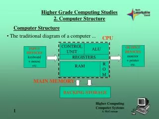
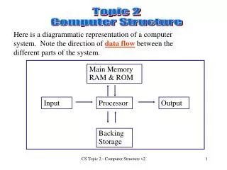
Topic 2 Computer Structure. Here is a diagrammatic representation of a computer system. Note the direction of data flow between the different parts of the system. Main Memory RAM & ROM. Input. Processor. Output. Backing Storage. 2.1 Buses.

Topic 2 Computer Structure
E N D
Presentation Transcript
Topic 2 Computer Structure Here is a diagrammatic representation of a computer system. Note the direction of data flow between the different parts of the system. Main Memory RAM & ROM Input Processor Output Backing Storage CS Topic 2 - Computer Structure v2
2.1 Buses The parts which go together to make up the computer system need to be able to communicate with one another. There are three sets of electrical lines which connect all the parts. These sets of lines are called buses. CS Topic 2 - Computer Structure v2
Addressability The Processor "sees" all the other parts of the computer, (ROM & RAM, Backing storage, Input and Output devices) as one continuous block of locations each with its own unique address. Each location has a different binary number which identifies it. This is its address. Giving every part of the computer a unique address allows the processor to communicate easily with any other part of the computer system and is known as addressability. CS Topic 2 - Computer Structure v2
The three buses which carry signals around the computer system each have their own particular function. 1. Address Bus This is used by the Processor to indicate which location has to be accessed. It is a one-way bus from the processor as the processor dictates all movement of signals. The number of lines on the address bus determines the maximum amount of memory locations which can be accessed. CS Topic 2 - Computer Structure v2
Address bus width and addressable memory 2 lines 00 01 10 11 A 2 line address bus would allow addresses. 4 because 22 = 4. A 3 line address bus would allow addresses. 8 because 23 = 8. 3 lines 000 001 010 011 100 101 110 111 X lines on the address bus allows addresses. 2x A 24 line address bus allows 224 = 16Mb of addresses. A 32 line address bus allows 232 = 4Gb of addresses. CS Topic 2 - Computer Structure v2
Calculating maximum memory size To calculate maximum memory size we need to consider two elements: the number of memory locations.(addresses) the size of each memory location. The following are assumed in the Higher course. The size of each memory location = data bus width = memory word size. CS Topic 2 - Computer Structure v2
Consider the following example: Calculate the maximum memory size of a computer with a 24 bit address bus and a memory word size of 16 bits. A 24 bit address bus allows 224 addresses = 16 MB of addresses. Each address contains 16 bits = 2 bytes Maximum memory size = 16 MB x 2 bytes = 32 MB CS Topic 2 - Computer Structure v2
2. Data bus This is the bus which is used to transfer the actual data to and from the locations. It is a two-way bus as data may be going to the processor (Read) or coming from the processor(Write). CS Topic 2 - Computer Structure v2
Control bus With both the data and the address buses, each of the lines operate together, in parallel, at the same time, as a unit. e.g. It would not make sense to look at one of the lines on the address bus. You have to look at them all to see the full address. The Control bus is a collectivename for a number of discrete lines each of which has a different function and operates at different times. They are best viewed as a number of individual lines. CS Topic 2 - Computer Structure v2
We’ll start with three of the lines on the control bus: 1. Read line The processor activates this line to show that it wants to be sent (read) data from another part of the computer system. 2. Write line The processor activates this line to show that it wants to send (write) data to another part of the computer system. • Clock line • This line sends a regular series of pulses at a speed measured in Hertz(Hz). Every event in the computer is timed to take place at particular points within the on/off cycle of each pulse. It controls the speed and timing of all operations in the computer. CS Topic 2 - Computer Structure v2
Other lines on the control bus include: 4. Reset line This line resets (clears the contents of all) the registers inside the processor. This prepares it for carrying out a new task. 5. Interrupt line Devices send a signal in on this line to interrupt the processor when they need attention. e.g. the printer may be out of paper. CS Topic 2 - Computer Structure v2
You have now seen the processor, main memory and three buses. The processor uses the three buses to communicate with the main memory. The processor works on data which is stored in main memory. It therefore spends a lot of time transferring data to and from the main memory. The two most basic operations which the processor carries out are and memory read memory write. CS Topic 2 - Computer Structure v2
Memory Read 1. Processor copies the required address onto the address bus. 2. Processor activates the read line on the control bus. 3. Memory controller copies the data from the required address onto the data bus and the data is transferred from the main memory to the processor. Memory Write 1. Processor copies the required address onto the address bus. 2. Processor copies the data onto the data bus. 3. Processor activates the write line on the control bus. 4. Memory controller copies the data from the data bus and puts it into the required memory location. CS Topic 2 - Computer Structure v2
2.2 Inside the processor The following components are generally found inside a Processor. Register Arithmetic & Logic unit. (ALU) Register Control Unit. (CU) Register Register The three buses(although not shown here) continue inside the processor to allow the components to communicate. CS Topic 2 - Computer Structure v2
Register 1. Registers A register is a storage location located inside the processor. A modern processor has many registers. Register Register Register Registers are used to hold : ●data which is being processed ●instructions which are being executed ●addresses which are about to be accessed. CS Topic 2 - Computer Structure v2
2. Control Unit (CU) Control Unit. (CU) The Control Unit (CU) is responsible for ● sending out the pulses on the control bus clock line to synchronise the timing of events and direct the fetching and executing of instructions. ● decoding the instructions when they arrive from the RAM and executing them. (i.e. carrying them out) CS Topic 2 - Computer Structure v2
3. Arithmetic & Logic Unit (ALU) Arithmetic & Logic unit. (ALU) The Arithmetic & Logic Unit is responsible for: ● carrying out the calculations on data being processed by a program. ● carrying out the logical decision making on data being processed by a program. This uses operators such as AND, OR, NOT. CS Topic 2 - Computer Structure v2
2.3 The Stored Program concept. Any problem can be solved by defining a sequence of instructions which are input and stored in RAM. A unit, called the , then fetches each instruction in turn and executes it. Processor The sets of instructions are called and the processor spends its time fetching and executing instructions one at a time. programs This is known as the fetch-execute cycle. CS Topic 2 - Computer Structure v2
2.4 The fetch-execute cycle. The steps in the fetch part of the cycle are always the same. 1. The processor sets up the with the address of the next instruction to be fetched. address bus 2. The processor sends a on the control bus. read signal data bus 3. The instruction is then copied onto the from the correct memory location to a register in the CPU. decodes 4. The CU(Control unit) the instruction and begins to it. execute The steps in the execute part of the cycle depend on the instruction to be executed. CS Topic 2 - Computer Structure v2
2.5 Memory A computer has to store data and instructions. It uses uses various types of memory to do this. Speed of access Registers fastest Cache memory Main memory Backing storage slowest CS Topic 2 - Computer Structure v2
Registers • The registers are storage locations located inside the processor. Registers Cache memory Main memory They allow the fastest access times as they are physically on the same chip as the processor. Backing storage Registers are used to hold : ●data which is being processed ●instructions which are being executed ●addresses which are about to be accessed. CS Topic 2 - Computer Structure v2
Cache memory • Cache memory is the second fastest type of memory. Registers Cache memory Main memory It is small amount of a fast type of Ram called static RAM(SRAM) which is used to store frequently accessed data and instructions. Backing storage The processor looks here for data before going out to the main memory. If the data is here then it can be very quickly accessed. Modern computers will have around 1 or 2 Mb of cache memory. CS Topic 2 - Computer Structure v2
Registers 3. Main memory Main memory is the third fastest type of memory. Cache memory Main memory It is made of a large amount of a type of Ram called dynamic RAM(DRAM) which is used to store programs and data. It also contains a small of amount of ROM for operating system use. Backing storage If the data or instructions cannot be found in the cache then the processor will access it from the main memory. Modern computers will have between 1 GB and 4GB of main memory. CS Topic 2 - Computer Structure v2
Registers 4. Backing Storage Backing storage is the slowest type of memory. It is needed because it keeps its contents even when the power is switched off unlike the types of memory listed so far. Cache memory Main memory Backing storage (except for ROM) Backing stores also tend to have a larger capacity than the faster types of memory. i.e. they can store more. There are many types of backing storage including Hard disk, DVD, CD,Floppy disk, magnetic tape, and solid state devices such as flash cards/memory sticks. The speed of access varies according to the backing store used. CS Topic 2 - Computer Structure v2
2.6 Computer Performance Measuring System performance How can you compare the performance of two computers? There are many ways to do this and some are better than others. We will be looking at four methods used for comparison: 1. Clock speed 2. MIPS 3. FLOPS 4. Application based tests CS Topic 2 - Computer Structure v2
1. Clock speed 2.6.1 Clock speed 2. MIPS 3. FLOPS 4. Application based tests The clock speed is often given as a measure of computer performance but it really only measures processor speed. It seems reasonable to assume that a Pentium IV 3.6 Ghz is faster than a Pentium IV 2.8 GHz. These processors are both made by Intel, have the same instruction set and basically work in the same way. When comparing different makes and types of processor, however, the one with the faster clock speed may not be “better”. The slower processor may work more efficiently. Comparing clock speeds alone is a poor measure of performance. CS Topic 2 - Computer Structure v2
1. Clock speed 2.6.1 Clock speed 2. MIPS 3. FLOPS 4. Application based tests Why can’t we just keep increasing the clock speed? • The processor can overheat and this will cause damage. • The other components may not be able to keep up with the processor and so “bottlenecks occur”. CS Topic 2 - Computer Structure v2
1. Clock speed 2.6.2 MIPS 2. MIPS 3. FLOPS 4. Application based tests (millions of instructions per second) MIPS measures how many instructions the processor executes per second. This seems like a good idea but different processors have different instruction sets and so they are difficult to compare. It doesn’t take into account the size and complexity of the instructions chosen for the tests. A manufacturer may choose a program with simple, fast instructions in it to make their processor look good. CS Topic 2 - Computer Structure v2
1. Clock speed 2.6.3 FLOPS 2. MIPS 3. FLOPS 4. Application based tests (floating point operations per second) This measure involves getting the processor to carry out floating point operations.(calculations on real numbers) and measures how many it can do each second. Floating point operations are carried out in the same way by most processors so this is a better method than clock speed or MIPS. FLOPS only measures calculating speed and does not consider the type of applications that a user may want to run on the computer. (programs) CS Topic 2 - Computer Structure v2
1. Clock speed 2.6.4 Application Based Tests 2. MIPS 3. FLOPS 4. Application based tests The best measure of performance involves running a set of tests using typical examples of commonly used applications. The tasks include loading large files, editing graphics, carrying out calculations etc. These are called benchmark tests and they show how well each processor can carry out specific tasks. (See handout) Computers are given a score for each test depending on how well they perform and so overall scores can be compared. This is a very realistic way of measuring performance. CS Topic 2 - Computer Structure v2
2.7 Performance factors The type of processor used plays a large part in determining system performance. However, other parts of the computer also have an effect on how well the computer performs. We will be looking at three factors which have an effect: 1. Data bus width 2. Cache memory 3. Data transfer rate to/from peripherals. CS Topic 2 - Computer Structure v2
1. Data bus width 2.7.1 Data bus width 2. Cache memory 3. Data transfer rate to/from peripherals Data and instructions are transferred using the data bus. A 64 bit data bus can carry twice as much data at a time as a 32 bit data bus. A wider data bus means that more data can be transferred at a time and this therefore improves system performance. This assumes that the other components e.g. registers can cope with the larger amounts of data. Also less fetches from RAM are required which also improves system performance. CS Topic 2 - Computer Structure v2
1. Data bus width 2.7.2 Cache memory 2. Cache memory 3. Data transfer rate to/from peripherals As you have already seen, cache memory is a small fast type of RAM which sits between the Processor and the main memory(RAM). Level 1 Cache is the fastest type of cache as it is physically on the same chip as the processor. Level 2 Cache is on a separate chip and so it is slower to access than Level 1. Both types are much faster than main memory RAM. Increasing the amount of cache memory improves the system performance. CS Topic 2 - Computer Structure v2
1. Data bus width 2.7.3 Data transfer rate to from/peripherals 2. Cache memory 3. Data transfer rate to/from peripherals A peripheralis any device that is not part of the essential computer. (the processor, memory, and bus paths). Some peripherals are mounted in the same case with the main part of the computer, e.g. the hard disk drive, DVD drive, and network interface card (NIC) Other peripherals are outside the computer case, e.g. the printer, mouse, keyboard,scanner, attached by a wired or wireless connection CS Topic 2 - Computer Structure v2
1. Data bus width Data transfer rate to from/peripherals 2. Cache memory 3. Data transfer rate to/from peripherals The processor communicates with peripheral devices. e.g. loading a file from a hard disk, scanning an image etc. Peripheral devices transfer at different speeds and so these can have an effect on system performance too. Peripheral device interfaces also transfer at different speeds. A hard disk drive spinning at 10000 rpm generally performs better than a 7200 rpm drive. (revolutions per minute) http://www.pcguide.com/ref/hdd/index.htm Using peripherals with fast data transfer rates will improve system performance. CS Topic 2 - Computer Structure v2
2.8 Current trends in Computer Hardware Computer technology is constantly improving with new ideas and techniques to improve performance. The following three trends have been seen for many years: 1. Increasing clock speeds 2. Increasing main memory 3. Increasing backing storage capacity. CS Topic 2 - Computer Structure v2
1. Increasing clock speeds 2.8.1 Increasing clock speeds 2. Increasing main memory 3. Increasing backing storage capacity. Clock speeds have increased rapidly over the years and are now measured in . Over the last year both and have announced that they will concentrate on other ways to improve system performance. Intel Gigahertz AMD A new desktop or laptop computer will have a processor with a clock speed of around 2.8 to 3.4 GHz. AMD processors tend to have slower clock speeds than Intel processors but AMD argue that their processors are more efficient. Have a look at the websites for current figures and products. www.intel.co.uk www.amd.com CS Topic 2 - Computer Structure v2
1. Increasing clock speeds 2.8.2 Increasing Main memory 2. Increasing main memory 3. Increasing backing storage capacity. The technology for making Main memory (RAM) continues to improve and capacity has increased while costs continue to fall. A new desktop or laptop computer will have between and of RAM fitted as standard. 1GB 4GB Increasing the amount of main memory(RAM) is a very effective way of improving system performance. If a computer does not have enough RAM then it has to make use of the Hard disk drive for temporary storage too. This is called and is much slower to access than RAM. virtual memory CS Topic 2 - Computer Structure v2
1. Increasing clock speeds 2.8.3 Increasing backing storage capacity 2. Increasing main memory 3. Increasing backing storage capacity. The technology for making Backing storage also continues to improve and capacity has increased while costs continue to fall. A new desktop computer will have a Hard disk drive of anywhere between and fitted as standard. 250 GB 1 TB Laptop computers tend to have smaller Hard disk drives with capacities from to 150 GB 500 GB . DVDs and solid state storage devices such as flash cards, memory sticks and memory cards also continue to increase in capacity while decreasing in price. CS Topic 2 - Computer Structure v2