Download
1 / 54
580 likes | 1.02k Views
System Hydraulics and Valve Engineering. Outline. Valve Definitions System Hydraulics Valve Flow Characteristics Valve Construction Valve Applications. Valve Definitions. A Valve is a mechanical device used to control flow or pressure in fluid systems.

E N D
Outline • Valve Definitions • System Hydraulics • Valve Flow Characteristics • Valve Construction • Valve Applications
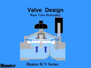
Valve Definitions A Valve is a mechanical device used to control flow or pressure in fluid systems. A Valve consists of a closure member (plug or disc) that is positioned inside of the valve body and can be operated manually or with an actuator.
On-Off Flow Control Pressure Control Non-Return Pressure Relief Directional Valve Types Super Backflow Prevention Assembly
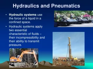
Fluids • Liquid • Gas • Slurry • Solids
Pressure A uniformly distributed force which is exerted in all directions. Pressure is measured in pounds per square inch (psig or psia). Head is feet of water column (ft). Differential Pressure is upstream pressure minus downstream pressure Delta P (psid). Also known as headloss.
Flow A moving volume of fluid at a velocity Gas Flow: Compressible, SCFM Liquid Flow: Incompressible, GPM SCFM = Std (0 psig, 60ºF) cubic feet per minute GPM = Gallons per minute FPS = Feet per second FPS = GPM x .4085 / D2
Pump Curves Pressure Flow
Surge (Water Hammer) A sudden change in pressure due to velocity changes. About 50 psi for every 1 fps change in velocity. The “hammer” is the pipe stretching and rebounding rapidly. H = a v / g where: H = pressure rise, ft a = wave velocity, ft/sec v = velocity change, ft/sec g = gravity, 32.2 ft/sec2
Critical Time The interval of time for a surge wave to travel the length of the system and return. T = 2 L / a where: T = critical time, sec L = length of pipe, ft. a = wave velocity, ft/sec
Critical Time Any change in flow velocity that occurs within the Critical Time has the same effect as if the change occurred instantaneously!
Surge Control • Air Valves can prevent air-related surges. • Vacuum Breakers can be used to create cushions of air at pipeline high points. • Check Valves must close very fast or very slow. • Fill pipelines slowly (i.e. 1 ft/sec). • Long pipelines need surge equipment or control valves operating slowly with the pump.
Surge Control OUCH!
Pressure Drop The difference between up and downstream pressures due to flow. Q = Cv (ΔP )½ ΔP = (Q / Cv )2 where: ΔP = pressure drop, psi Cv = flow coefficient Q = flow rate, gpm
Pressure Drop Various TDCV Cv’s: 6” 1160 12” 5400 24” 25,500 48” 119,000 NOTE: A 6” Valve can handle 1600 GPM TDCV
Headloss Pressure drop expressed in feet of water column. ΔH = K v2 / 2 g where: ΔH = headloss, ft. of water column K = flow coefficient v = flow velocity, ft/sec g = gravity, 32.2 ft/sec2
Headloss Various K Values: 90 Degree Elbow: 0.4 Butterfly Valve: 0.4 Tilted-Disc Check Valve: 0.5 Plug Valve: 0.8 Swing Flex Check Valve: 0.9 Silent Check Valve: 3.0 1000 feet of pipe: 15.0 Silent Check Valve
Headloss Competitor’s BFV 150B Flow Coefficients, K. SizeVal-MaticPrattDeZurik 12” .43 .45 .56 24” .40 .30 .56 48” .36 .22 .40 72” .34 .23 .38
Energy Costs Head Loss costs money in additional pumping costs: GPM x ΔH x Sg x C/Kwh x 1.65 EC/Y = PE x ME Where: EC/Y = energy cost per year, $/year Sg = specific gravity, water = 1.0 C/Kwh = cost of electricity, $/Kw-hr PE = pump efficiency, (.85 typical) ME = motor efficiency, (.85 typical)
Energy Example A 12” TDCV is used to replace a 12” control valve. The TDCV has a headloss of 0.7 ft. and the control valve, 2.9 ft. Based on an energy cost of $.08 per Kw-hr, what is the cost savings by using a TDCV for (6) 3200 gpm pumps operating 50% of the time? 3200 x (2.9-0.7) x 1 x .08 x 1.65 EC/Y = .85 x .85 = $1286 For (6) valves at 50% operation for 40 years: Total cost savings = $1286 x 6 x .50 x 40 = $154,320
Inherent Flow Characteristics Quick-Open Linear Equal Percentage CLOSED OPEN
Inherent Flow Characteristics % Cv % Open
Installed Flow Characteristics 5000 ft. 500 ft. 12” Butterfly OPEN CLOSED
Installed Flow Characteristics 12” BFV, 500 ft. 8” BFV, 500 ft. CLOSED OPEN
Actuator Operating Statistics OPEN VALVE POSITION Worm Gear Traveling Nut CLOSED ACTUATOR STROKE
Cavitation • Cavitation is the vaporization and subsequent violent condensation of a liquid due to localized low pressure areas in a piping system. • Cavitation sounds like rocks flowing through the valve. • Continuous Cavitation will shorten the life of the valve and piping system.
Cavitation A Cavitation Index can be calculated to predict whether cavitation will occur as follows: σ = (Pu – Pv) / (Pu – Pd) where: σ = cavitation index, dimensionless Pd = downstream pressure, psig Pv = vapor pressure (-14.2 psig at 60ºF) Pu = upstream pressure, psig The lower the index, more likely Cavitation
Cavitation For Example, an 8” plug valve is used in a backwash system to limit flow rate with an upstream pressure of 11 psig and a downstream pressure of 5 psig and a throttled position of 22 degrees open. σ = (Pu – Pv) / (Pu – Pd) σ = (11 – (-14.2)) / (11 – 5) σ = 4.2
Cavitation Cavitation Free Zone Cavitation
Pressure Classes Pressure Class does not a Pressure Rating Make! AWWA Class 150A: 150 psig, 8 fps AWWA Class 250B: 250 psig, 16 fps ANSI Class 125 Gray Iron: 150 psig ANSI Class 250 Gray Iron: 300 psig ANSI Class 150 Ductile Iron: 250 psig ANSI Class 300 Ductile Iron: 640 psig ANSI Class 150 Steel: 285 psig ANSI Class 300 Steel: 740 psig
Valve End Types • Flanged: ANSI, ISO, DIN, AS, BS • Mechanical Joint: AWWA C111 • Push-On (i.e. Tyton) • Threaded: NPT, BSPT • Grooved, Shouldered, Victaulic
Material Properties Ductile Iron ASTM A536 Grade 65-45-12 American Society of Testing and Materials (ASTM) Tensile Strength: 65,000 psi Yield Strength: 45,000 psi Elongation: 12% (Ductile) Hardness: 170 BHN Shrinkage: 1/16” per foot Chemistry: Iron, Silicon, Carbon, Sulfur, Magnesium
Material Properties Ductile Iron Gray Iron
Body and Disc Materials Gray Iron: ASTM A126 Class B Ductile Iron: ASTM A536 Gr. 65-45-12 Cast Steel: ASTM A216 Gr. WCB Cast SS: ASTM A351 Gr. CF8M (316 SS)
Trim Materials • Cast SS: ASTM A216 Gr. CF8M (316 SS) • SS Bar: ASTM A276, Type 316 • 17-4 Bar: ASTM A564, Gr. 630, Cd H1150 • Bronze: ASTM B584 C83600 (85-5-5-5) • Alum. Brz: ASTM B271 C95400
Seal Materials • Buna-N (NBR, Nitrile, Hycar) 200ºF • Viton (FKM, Fluorocarbon) 400ºF • Natural Rub (NR, Poly-Isoprene) 200ºF • Neoprene (CR, Chloroprene) 250ºF • EPDM (Ethylene Propylene) 250ºF • Hypalon (Chlorosulfonated PE) 250ºF Temperature, Durometer, Compatibility
Corrosion • Water should be in the 6.5-10 PH range • Chlorine content should be less than 2 ppm • Brackish or salt water is corrosive to irons • All SS or DI/FBE for salt and mine water
Coatings and Linings • Corrosion Inhibitor (Fernox), 0 mils • Universal metal primer, 3 mils • Black Asphaltic, 3 mils • Polyamide 2-part epoxy, 6 mils • Fusion Bonded Epoxy (FBE), 10 mils • Linings of Natural Rubber or Teflon, 1/8”
Installation Matters • Upstream disturbances affect valve performance. • Pressures and flows must be within ratings. • Unusual fluids can cause corrosion or safety issues. • Pressure direction affects actuator sizing and performance. • Vertical flow changes the operation of check valves. • DDCV Series 8900 is the only check valve for air service. • Air valves freeze. • Discs and stems can interfere with the adjacent valves.
Installation Matters • Upstream disturbances affect valve performance. • Pressures and flows must be within ratings. • Unusual fluids can cause corrosion or safety issues. • Pressure direction affects actuator sizing and performance. • Vertical flow changes the operation of check valves. • DDCV Series 8900 is the only check valve for air service. • Air valves freeze. • Discs and stems can interfere with the adjacent valves.
Installation Matters • Upstream disturbances affect valve performance. • Pressures and flows must be within ratings. • Unusual fluids can cause corrosion or safety issues. • Pressure direction affects actuator sizing and performance. • Vertical flow changes the operation of check valves. • DDCV Series 8900 is the only check valve for air service. • Air valves freeze. • Discs and stems can interfere with the adjacent valves.
Installation Matters • Upstream disturbances affect valve performance. • Pressures and flows must be within ratings. • Unusual fluids can cause corrosion or safety issues. • Pressure direction affects actuator sizing and performance. • Vertical flow changes the operation of check valves. • DDCV Series 8900 is the only check valve for air service. • Air valves freeze. • Discs and stems can interfere with the adjacent valves.
Installation Matters • Upstream disturbances affect valve performance. • Pressures and flows must be within ratings. • Unusual fluids can cause corrosion or safety issues. • Pressure direction affects actuator sizing and performance. • Vertical flow changes the operation of check valves. • DDCV Series 8900 is the only check valve for air service. • Air valves freeze. • Discs and stems can interfere with the adjacent valves.
Installation Matters • Upstream disturbances affect valve performance. • Pressures and flows must be within ratings. • Unusual fluids can cause corrosion or safety issues. • Pressure direction affects actuator sizing and performance. • Vertical flow changes the operation of check valves. • DDCV Series 8900 is the only check valve for air service. • Air valves freeze. • Discs and stems can interfere with the adjacent valves.
Installation Matters • Upstream disturbances affect valve performance. • Pressures and flows must be within ratings. • Unusual fluids can cause corrosion or safety issues. • Pressure direction affects actuator sizing and performance. • Vertical flow changes the operation of check valves. • DDCV Series 8900 is the only check valve for air service. • Air valves freeze. • Discs and stems can interfere with the adjacent valves.