Download
1 / 23
790 likes | 1.44k Views
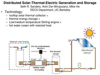
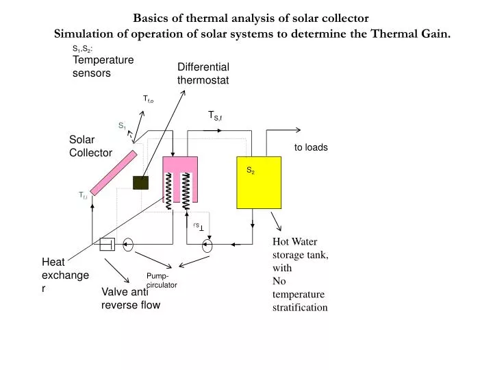
S 1 ,S 2 : Temperature sensors. Differential thermostat. Τ f,ο. T S,f. S 1. Solar Collector. to loads. S 2. Τ f,i. Τ S, i. Hot Water storage tank, with No temperature stratification. Heat exchanger. Προς φορτίο. Pump-circulator. Valve anti reverse flow.

E N D
S1,S2: Temperature sensors Differential thermostat Τf,ο TS,f S1 Solar Collector to loads S2 Τf,i ΤS,i Hot Water storage tank, with No temperature stratification Heat exchanger Προς φορτίο Pump-circulator Valve anti reverse flow Basics of thermal analysis of solar collector Simulation of operation of solar systems to determine the Thermal Gain.
The useful thermal energy Qu can be calculated from the relation: (1.1) or normalized to solar collector surface, the thermal power output is given by: (1.2)
(1.3) A similarity to the previous expressions holds for the hot water tank,too: It can be also shown that the useful thermal gain from a solar collector is given by: (1.4) orequivalently (1.5)
The coefficient of effectiveness, ε, is given by an expression in any Heat Transfer book, (1.6) From the expression (1.2) of calorimetry one gets: • (1.7)
SubstituteTf,ifrom (1.7) to (1.3), then the equation which provides the Thermal Power stored in the system-tank takes the form: (1.8) We solve eq. (1.5 ) for Tf,oand we get: (1.9)
Basics of thermal analysis of solar collectors & Simulation of operation of solar systems to determine the Thermal Gain. Prof. Socrates Kaplanis
References Renewable Energy Systems : Theory and Intelligent Applications Editors : S.Kaplanis, E.Kaplani Nova Science Publishers, N.Y. , 2012
Substitution of Tf,oto (.1.8), gives: (1.10) The expression (1.10) can be easily simplified to: (1.11)
We define a new parameter, F΄R: (1.12) Hence, the expression (1.11) is simplified as to: (1.13)
Let us consider a small time period the solar collector system operates. Then, the mean water temperature in the storage tank is determined by: (1.14) The heat delivered by a collector, Αc, in a period, Δτ , to the tank may be determined by: (1.15)
We divide both sides of (.1.15) over Αc to normalize the expression. Then (1.16) or equivalently (1.17)
Substitute Τs,f from (1.17) to (1.14). We get: (1.18) Τsis the mean temperature of the waterin the tank in the above time interval.Integration of (1.13 or 1.15) for this time period gives: (1.19)
Let us analyze a real case A Solar Collector System, as the one shown in the 1st figure, has parameters: F`RUL=3.5 W/m^2*K and F`R(τα)n= 0.69 and is placed at horizontal position in Pyrgos. The storage tank has capacity 50 l/m^2. Let the storage tank temperature at 7:30 be 20 C. Please determine the hourly temperature in the tank and the hourly efficiency. Data input: ambient temperature , Ta, and the mean hourly global solar radiation, Hn. Values are given in theTable below
Data input and values of basic quantitiesas provided by the iteration procedure to be outlined below.
To determine the quantities Τs,f ,Τs.i Α. Time Interval 7:30 – 8:30 am Step 1st : We determine the normalized useful heat by (1.20). (1.21)
Step 2nd : We determine tank temperature, Τs,f, at the end of the 1st interval 8:30 amusing expression (1.17) (1.22) Step 3rd : Determine efficiency, η, during this short period by : (1.23)
Β. Time Interval 8:30 – 9:30am We follow the same procedure as before. We put for this period 8:30-9:30 as Τs,i, the Τs,f value of the previous interval. Determine from (1.20) (1.24)
Determine Τs,ffrom (1.17) (1.25) Then, the efficiency is estimated by: (1.26)
S1,S2: temperature sensors Back up source outside the tank Hot Water For use Flat plate Solar collectors ~ S1 S2 Back up electric source in the tank serpantine Differential thermostat Hot Water storage tank Valve to prevent reverse flow Pump circulator
2. A generalized analysis to consider the Load, too. Let us consider qs as the net stored heat normalized to collector surface; that is when the Load, QL, is subtracted.Correspondingly, the thermal load per collector surface is denoted by, ( qL =QL/Ac). Then it holds : (2.1) Following the procedure as for expression (1.18) there is given that: (2.2)
2. A generalized analysis to consider the Load, too. Substitute Τs to (1.19). Then, the expression (1.20) is modified and due to (2.1) we get : (2.3) We substitute (2.3) in (2.1) and we finally get the generalized iterative formula: (2.4)
References Renewable Energy Systems: Theory and Intelligent Applications Editors S. Kaplanis, E. Kaplani Nova Science Publishers, N.Y., 2012