Download

1 / 24
250 likes | 449 Views
Stephen J Dodds School of Computing and Technology. Jan Vittek University of Zilina Slovakia. Sliding Mode Control of PMSM Drives Subject to Torsional Oscillations in the Mechanical Load. OVERVIEW OF PRESENTATION. Motivation Brief overview of sliding mode control The plant and its model

E N D
Stephen J Dodds School of Computing and Technology Jan Vittek University of Zilina Slovakia Sliding Mode Control of PMSM Drives Subject to Torsional Oscillations in the Mechanical Load
OVERVIEW OF PRESENTATION • Motivation • Brief overview of sliding mode control • The plant and its model • The case for separate single input, single output sliding mode controllers • Formulation of a practicable general sliding mode controller • Plant rank determination for correct SMC selection • Zero dynamics for rotor angle control • The set of three sliding mode controllers • Presentation of simulation results • Conclusions and recommendations
MOTIVATION OF THE RESEARCH The tuning needed for conventional motion controllers at the commissioning stage and whenever changes in the driven mechanical load occur is, in general, very time consuming and requires knowledge and experience of dynamical systems and control. When significant mechanical vibration modes are present this problem is not only exacerbated but it may not even be possible to tune conventional controllers to attain satisfactory performance. Through its non-reliance on plant models, sliding mode control has been investigated with a view to finding a simple solution readily acceptable in industry.
Switching boundary in r-1 dimensional error space: ‘n’ region: Brief Overview of Sliding Mode Controlfor Single Input, Single Output Plants ‘p’ region: Derivative Estimator Basic sliding mode controller:
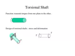
The Plant Model:The Two-Mass, one Motor System Load inertia Two control problems will be addressed:a) The control of the rotor angle.b) The control of the load mass angle. both in the presence ofan external load torque applied to the load mass. Flexible shaft(torsional compliance) Motor rotor inertia
External load mass load torque Mechanical Part: Load moment of inertia Rotor moment of inertia Spring constant Electro-magnetic torque Inertial datum External rotor load torque, Electrical Part: Control Variables Plant Model
Complete Block Diagram Model of Plant As will be seen, despite the interaction in the plant rendering the control problem a multivariable one, separate single input, single output sliding mode control loops will suffice. The argument for this will be presented next.
Single Input, Single Output Sliding Mode Controllers The signal, B wr Iq, may be regarded as a disturbance input to the direct axis current control loop. So the plant simplifies to the following for the direct axis current control: It is now clear that a single input, single output sliding mode controller may be designed for controlling id using ud. This leaves only qr or qL to be controlled using uq. This may also be achieved by single input, single output sliding mode controllers.
The closed-loop phase portrait and a typical trajectory are illustrated here for r = 2: Derivative Estimator Switching Boundary Formulation of Practicable Sliding Mode Controller First, return to the basic sliding mode controller:
The problem with this is that the control chatter during the sliding motion may interact adversely with the switching of the inverter, so the control accuracy and stator current waveforms could be poor. Boundary Layer Switching Boundary To overcome this problem, the control chatter may be eliminated by replacing the switching boundary with a boundary layer giving a continuoustransition of u between –umax and +umax between the sides of the boundary : Formulation of Practicable Sliding Mode Controller
Ideal Differentiator Ideal Differentiator Ideal Differentiator Formulation Practicable Sliding Mode Controllers An ‘Ideal’ derivative estimator would amplify high frequency components of measurement noise. This problem may be overcome, however, by combining a low pass filter with each differentiator, but there is a trade-off between the degree of filtering and robustness of the SMC.
Ideal Differentiator Ideal Differentiator Ideal Differentiator Formulation Practicable Sliding Mode Controllers An ‘ideal’ derivative estimator would amplify high frequency components of measurement noise. This problem may be overcome, however, by combining a low pass filter with each differentiator, but there is a trade-off between the degree of filtering and robustness of the SMC.
ri = 1 Plant Rank Determination for SMC Design To determine the rank w.r.t. a selected output, the number of integrators in each forward path from every control input and that output may be counted. Rank w.r.t. id:: Then the rank is equal to the smallest integrator count.
Plant Rank Determination for SMC Design To determine the rank w.r.t. a selected output, the number of integrators in each forward path from every control input and that output may be counted. Rank w.r.t. qr:: rq = 3 Then the rank is equal to the smallest integrator count.
Hence minimum integrator count to the output,qL , is 5. rL = 5 Minimum integrator count = 3 to this point Plant Rank Determination for SMC Design To determine the rank w.r.t. a selected output, the number of integrators in each forward path from every control input and that output may be counted. Then the rank is equal to the smallest integrator count. Rank w.r.t. qL::
Zero Dynamics for Rotor Angle Control Suppose qr has been brought to zero by the sliding mode controller. Then an uncontrolled subsystem may be identified in the plant block diagram, as follows: The only input to this subsystem is GLeonce qr = 0. So the remainder of the plant can be ignored. 0
The only input to this subsystem is GLeonce qr = 0 and the remainder of the plant is ignored. The characteristic equation of this subsystem, from the determinant of Mason’s formula, is: The eigenvalues (poles) of this uncontrolled subsystem are therefore 0 Hence the subsystem is subject to uncontrolled oscillations at a frequency of In simple terms, the control system holds the rotor fixed but allows the load mass to oscillate, restrained by the torsion spring but without damping. Zero Dynamics for Rotor Angle Control Suppose qr has been brought to zero by the sliding mode controller. Then an uncontrolled subsystem may be identified in the plant block diagram, as follows:
For rotor angle control, rr = 3, so the order of the highest derivative to feed back is rr – 1 = 2. The first derivative is the rotor speed and assumed to be produced by the shaft encoder software, so a derivative estimator is only needed for the second derivative. The closed loop dynamics is of second order. The Set of Sliding Mode Controllers For direct axis current control, ri = 1, so the order of the highest derivative to feed back is ri – 1 = 0. In this case no output derivatives are needed and the ideal SMC has no closed loop dynamics. The practicable version of the SMC then reduces to a simple proportional controller with a high gain.
The Set of Sliding Mode Controllers For load mass angle control, rL = 5, so the order of the highest derivative to feed back is rL – 1 = 4. The first derivative is the load mass angular velocity and assumed to be produced by the shaft encoder software, so a derivative estimator is only needed for the second, third and fourth derivatives. The closed loop dynamics is of fourth order.
PARAMETERS FOR SIMULATION Motor Load Controller
CONCLUSIONS AND RECOMMENDATIONS • The simulations predict robustness for sliding mode control of rotor angle and also load mass angle in that the ideal responses are followed with moderate accuracy. • The differences between the simulated and ideal responses are attributed to the finite gains of the control saturation elements within the boundary layers. • The vector control condition of keeping the direct axis stator current component to negligible proportions is very effectively maintained. • It is recommended that the potential accuracy of the method is ascertained by exploring the design limits regarding sampling frequency, saturation element gain, and the derivative estimation filtering time constant, in the presence of measurement noise. • Other derivative estimation methods should also be investigated, such as the high gain multiple integrator observer. • Extension to the control of mechanisms with more than one uncontrolled vibration mode would be of interest. • The results obtained here are sufficiently promising to warrant experimental trials, which will attract potential industrial users.