Download
1 / 30
300 likes | 432 Views
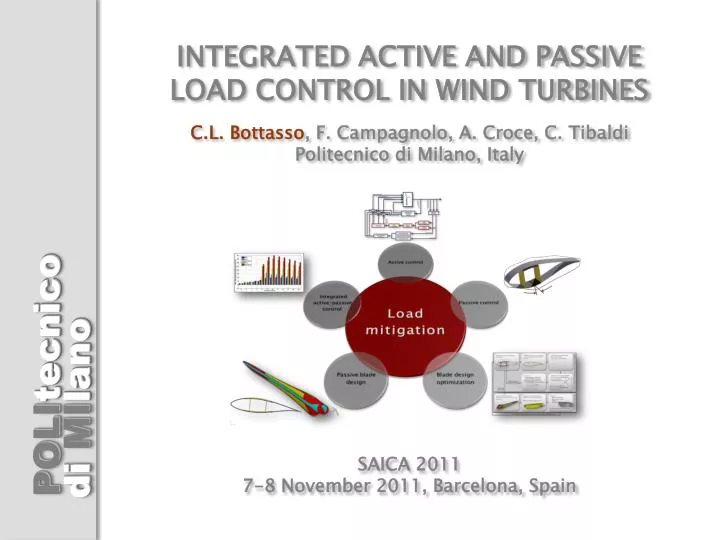
INTEGRATED ACTIVE AND PASSIVE LOAD CONTROL IN WIND TURBINES C.L. Bottasso , F. Campagnolo , A. Croce, C. Tibaldi Politecnico di Milano, Italy SAICA 2011 7-8 November 2011, Barcelona, Spain. Need for Load Mitigation. Trends in wind energy : Increasing wind turbine size ▶ Off-shore wind ▼.

E N D
INTEGRATED ACTIVE AND PASSIVE LOAD CONTROL IN WIND TURBINESC.L. Bottasso, F. Campagnolo, A. Croce, C. TibaldiPolitecnico di Milano, ItalySAICA 20117-8 November 2011, Barcelona, Spain
Need for Load Mitigation • Trends in wind energy: • Increasing wind turbine size ▶ • Off-shore wind ▼ • To decrease cost of energy: • Reduce extreme loads • Reduce fatigue damage • Limit actuator duty cycle • Ensure high reliability/availability
Active Load Mitigation: Pitch Control • Individual blade Pitch Control (IPC) • Inner loop (collective pitch): regulation to set point and alleviation of gust loads • Outer loops (individual pitch): reduction of • Deterministic (periodic) loads due to blade weightand non-uniform inflow • Non-deterministicloads, caused by fast temporal and small spatial turbulent wind fluctuations • ▼ Uniform wind ▼ Turbulent wind
Active Load Mitigation: Predictive LiDAR-Enabled Pitch Control • LiDAR: generic model, captures realistically wind filtering due to volumetric averaging • Receding Horizon Control: model predictive formulation with wind scheduled linear model, real-time implementation based on CVXGEN • Non-Homogeneous LQR Control: approximation of RHC, extremely low computational cost LiDAR prediction span Reduced peak values Reduced peak values Reduced peak to peak oscillations
Active Load Mitigation: Distributed Control • Flow control devices: • TE flaps • Microtabs • Vortex generators • Active jets (plasma, synthetic) • Morphing airfoils • … • (Credits: Risoe DTU) • (Credits: Risoe DTU) • (Chow and van Dam 2007) • (Credits: Smart Blade GmbH)
Active Load Mitigation: Limits and Issues • Pitch control: • Limited temporal bandwidth (max pitch rate ≈ 7-9 deg/sec) • Limited spatial bandwidth (pitching the whole blade is ineffective for spatially small wind fluctuations) • Distributed control: • Alleviate temporal and spatial bandwidth issues • Complexity/availability/maintenance • Sensor-enabled control solutions: • Complexity/availability/maintenance • Off-shore: need to prove reliability, availability, low maintenance in hostile environments
Passive Load Mitigation • Passive control: loaded structure deforms so as to reduce load • Two main solutions: • Potential advantages: no actuators, no moving parts, no sensors • Other passive control technologies (not discussed here): • Tuned masses (e.g. on off-shore wind turbines to damp nacelle-tower motions) • Passive flaps/tabs • … • Bend-twist coupling (BTC): exploit anisotropy of composite materials • - Swept (scimitar) blades Angle fibers in skin and/or spar caps
Objectives • Present study: • DesignBTC blades (all satisfying identical design requirements: max tip deflection, flap freq., stress/strain, fatigue, buckling) • Consider trade-offs (load reduction/weight increase/complexity) • Identify optimal BTC blade configuration • Integratepassive BTC and active IPC • Exploit synergiesbetween passive and active load control • Baseline uncoupled blade: 45m Class IIIA 2MW HAWT
Optimization-Based Multi-Level Blade Design • Optimizer • Local/global solvers (SQP, GA) • Functional approximators • Cost: • AEP • Aerodynamic parameters: • chord, twist, airfoils Cp-Lambda aero-servo-elastic multibodysimulator 2D ANBA cross sectional analyzer 3D FEM models Parameters • Cost: • AEP/weigh (or cost model if available) • Macro parameters: • rotor radius, max chord, tapering, … Cost function & constraints • Cost: • Blade weight (or cost model if available) • Structural parameters: • thickness of shell and spar caps, width and location of shear webs • Controls: • model-based (self-adjusting to changing design)
“Coarse” level: 2D FEM section & beam models - ANBA 2D FEM sectional analysis - Computation of 6x6 stiffness matrices Definition of sectional design parameters - Definition of geometrically exact beam model - Span-wise interpolation - Definition of complete HAWT Cp-Lambda multibodymodel - DLCs simulation - Campbell diagram DLC post-processing: load envelope, DELs, Markov, max tip deflection • Constraints: • - Maximum tip deflection • - 2D FEM ANBA analysis of maximum stresses/strains • - 2D FEM ANBA fatigue analysis • - Compute cost (mass) SQP optimizer min cost s.t. constraints When SQP converged “Fine” level: 3D FEM Automatic 3D CAD model generation by lofting of sectional geometry Automatic 3D FEM meshing (shells and/or solid elements) Update of blade mass (cost) • Analyses: • - Max tip deflection • - Max stress/strain • - Fatigue • - Buckling • Verification of design constraints Constraint/model update heuristic (to repair constraint violations)
2MW 45m Wind Turbine Blade Currently undergoing certification at TÜVSÜD • CNC machined model of aluminum alloy for visual inspection of blade shape Design developed in partnership with Gurit (UK)
Fully Coupled Blades • Identify optimal section-wise fiber rotation • Consider 6 candidate configurations • BTC coupling parameter: Skin angle Spar-cap angle
Fully Coupled Blades: Effects on Weight Spar-caps: steep increase Skin: milder increase Spar-cap/skin synergy • Stiffness driven design (flap freq. and max tip deflection constraints): • Need to restore stiffness by increasing spar/skin thickness
Spar-cap/skin synergy: good load reduction with small mass increase Fully Coupled Blades: Load Reduction
Fully Coupled Blades: Effects on Duty Cycle • ◀ Less pitching from active control because blade passively self-unloads • Much reduced life-time ADC ▶
Partially Coupled Blades • Identify optimal span-wise fiber rotation: 5 candidate configurations Reduce fatigue in max chord region Avoid thickness increase to satisfy stiffness-driven constraints
Partially Coupled Blades: Effects on Mass Fully coupled blade Too little coupling
Partially Coupled Blades:Effects on Loads F30: load reduction close to fully coupled case
Partially Coupled Blades:Effects on Duty Cycle • Best compromise: similar load and ADC reduction as fully coupled blade, decreased mass
Integrated Passive and Active Load Alleviation • Individual blade pitch controller (Bossaniy 2003): • Coleman transform blade root loads • PID control for transformed d-q loads • Back-Coleman-transform to get pitch inputs Baseline controller: MIMO LQR
Integrated Passive and Active Load Alleviation • Two IPC gain settings: • Mild: some load reduction, limited ADC increase • Aggressive: more load reduction, more ADC increase • Five blade/controller combinations: • BTC: best coupled blade + collective LQR • IPC1: uncoupled blade + mild IPC • BTC+IPC1: best coupled blade + mild IPC • IPC2: uncoupled blade + aggressive IPC • BTC+IPC2: best coupled blade + aggressive IPC
Integrated Passive/Active Control:Effects on Loads • ▲ Synergistic effects of combined passive and active control ▶
Integrated Passive/Active Control:Effects on Duty Cycle Not significant: ADC very small here Same ADC as baseline (but great load reduction!)
Conclusions • Optimization-based blade design tools: enable automated design of blades and satisfaction of all desired design requirements • BTC passive load control: • Skin fiber rotation helps limiting spar-cap fiber angle • Partial span-wise coupling limits fatigue and stiffness effects • Reduction for all quality metrics: loads, ADC, weight • Combined BTC/IPC passive/active control: • Synergistic effects on load reduction • BTC helps limiting ADC increase due to IPC (e.g., could have same ADC as baseline blade with collective pitch control) • Outlook: • Manufacturing implications of BTC and partially coupled blades • Passive distributed control and integration with blade design and active IPC control