Download
1 / 30
300 likes | 455 Views
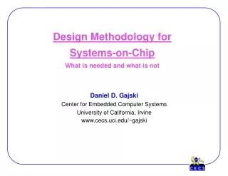
Design Methodology for Systems-on-Chip What is needed and what is not. Daniel D. Gajski Center for Embedded Computer Systems University of California, Irvine www.cecs.uci.edu/~gajski. Who we are?. Center for Embedded Computer Systems (www.cecs.uci.edu)

E N D
Design Methodology forSystems-on-ChipWhat is needed and what is not Daniel D. Gajski Center for Embedded Computer Systems University of California, Irvine www.cecs.uci.edu/~gajski
Who we are? • Center for Embedded Computer Systems (www.cecs.uci.edu) • Independent Research Organization in UC • 15 faculty and over 60 Ph.D. students • Methodology group: • first system contract 1989 from SRC • over 50 person years in system methodology since 1990 • over 10 Ph.D. in system design flow since 1990 • published first books on: • RTL Sythesis 1992 • Embedded Systems 1994 • System Design 2001 • developed SpecC language • leaders in SpecC Open Technology Consortium (www.specc.org) • “Inspired” SystemC
Outline • System gap • Semantics, styles and refinements • RTL Semantics • System-Level Semantics • Where are we going? • Conclusion
Capture & Simulate Specs Algorithms System Gap Design Logic Simulate Physical Manufacturing 1960’s Past Design Flow
Capture & Simulate Describe & Synthesize Specs Specs Algorithms (software) Algorithms Design Design Logic Logic Physical Physical Manufacturing Manufacturing 1960’s 1980’s Past and Present Design Flow System Gap Describe Simulate Simulate
Capture & Simulate Describe & Synthesize Specify, Explore & Refine Executable Spec Functionality Specs Specs Algorithms (software) Algorithms Algorithms Connectivity Architecture Protocols Design Design Design Timing Logic Logic Logic Physical Physical Physical Manufacturing Manufacturing Manufacturing Past, Present and Future Design Flow System Gap Communications Describe Simulate Simulate 1960’s 1980’s 2000’s
Simulatable but not synthesizable 3.415 2.715 case X is when X1 => when X2 => Finite State Machine Table Lookup Controller Memory Missing Semantics:Simulation Dominated Design Flow
Behavior Structure Synthesis Physical Design Physical Y Chart
Behavior Structure System RTL Logic Transistor Physical Y Chart
Behavior Structure System RTL Logic MoC MoC MoC Transistor MoC Physical Y Chart
Abstraction Algebra Algebra := < {objects}, {operations} > SoC Algebra := < {models}, {transformations} > Ordered set of transformations < tm, … , t2, t1> is a refinement iff model B = tm( … ( t2( t1( model A ) ) ) … ) Question: { models } ? ; { transformations } ?
Why Abstraction Algebra? 1. Enabling standard for ESDA 2. Discover truth behind system-level myths 3. Define system-level field (abstract semantics) 4. Introduce interoperability 5. Identify system-level methodology 6. Apply system-level methodology to SystemC, SpecC and others.
Semantics, Styles & Refinements • Each model uses well defined semantics • Each model has simple style • Each style uniquely expressed • no syntactic variance or semantic ambiguity • Each model needs style checker • Each model can be refined from its predecessor • Clear refinement rules • Clear application order of refinement rules • Model refinements are verifiable
S1 S2 Op1 Op2 Op3 Op4 S3 Op5 Op6 Op1 Op2 Op1 Op2 Op3 RTL Computational Models • Finite State Machine with Data (FSMD) • Combined model for control and computation • FSMD = FSM + DFG • Implementation: controller plus datapath FSMD model
Data memory Control inputs Cotrol signals Selector IR D Q Register Cache RF D Q Bus1 Bus2 Next- Sate Logic or Address generator D Q Output logic or Program memory State register or PC ALU Latch Bus3 SR Signal status Register Controller Datapath Control outputs Datapath outputs RTL Processor
RTL Data memory Control inputs Control signals IR Selector D Q Register Memory D Q Bus1 Next- state logic or Address generator Bus2 D Q Output logic or Program memory Op1 Op2 RF Op1 Op2 Op3 State register or PC ALU S1 S2 Latch Bus3 Op4 SR Signal status Register Op1 Op2 S3 Op5 Op6 Controller Datapath Op3 Control outputs Datapath outputs FSMD model RTL Processor RTL Synthesis
RTL Data memory Control inputs Control signals Op1 Op2 RF Op1 Op2 Op3 IR Selector D Q S1 S2 Register Memory D Q Op4 Bus1 Op1 Op2 Next- state logic or Address generator S3 Bus2 D Q Op5 Op6 Output logic or Program memory State register or PC ALU Op3 Latch Bus3 SR Signal status Register Controller Datapath RTL Processor Control outputs Datapath outputs RTL Synthesis Variable binding Operation Binding Rescheduling Bus Binding Allocation FSM Synthesis FSMD model
Proc Proc Proc Proc Proc System Computational Models • Program State Machine • States described by procedures in a programming language • Example: SpecC! (SystemC!) PSM model
System µProcessor IP Memory Comp. Proc Proc Proc Interface Interface Proc Proc Bus Interface Interface Memory Custom HW System architecture PSM model System Synthesis
System System Semantics Objects: - Behaviors - Channels Composition: - Hierarchy - Order • Sequential • Parallel • Piped • States - Transitions • TI • TOC, TOS, ... - Synchronization Objects: - Components • Proc • IP • Memories • IF - Connections • Buses • Wires Composition: (same as in Behavior Model)
µProcessor IP Memory Comp. Proc Proc Proc Interface Interface Proc Proc Bus Interface Interface Memory Custom HW System architecture PSM model System Synthesis Variable Binding Behavior Binding Channel Binding Allocation IF Synthesis Profiling Refinement System
RTL Control Pipeline IF FSM IP Netlist RAM State MoC PC FSMD1 FSMD3 IR FSMD5 FSMD2 FMDS4 Control Datapath IF FSM Memory Mem RF State State ALU RTL/IS Implementation + results HCFSMD model System Synthesis (continued)
EDA Approach: Simulation System RTL Logic VHDL, Verilog, Transistor
System RTL Logic Transistor C++ Approach: Syntax
MoC System RTL Logic Transistor MoC Approach: Diversity
SystemC C++ C Supported Subset SystemC Approach: Language First Source: J. Kunkel, VP Synopsis, (CODES, May 2002)
System MoC RTL Logic Transistor SpecC Approach: Semantics First
SystemC/SpecC SystemC C++ C SpecC
Quote from SystemC FUNCTIONAL SPECIFICATION FOR SYSTEMC 2.0 Version 2.0-M January 17, 2001 1.8 ACKNOWLEDGEMENTS “Many companies and individuals have contributed time and resources in the development of both SystemC 1.0 and SystemC 2.0. Some of these contributors are listed in the contributors section of this specification and in the SystemC 1.0 Users’s Guide. It should be noted that the fundamental mechanisms used to model communication and synchronization in SystemC 2.0 - interfaces, channels, and events - were inspired by similar constructs in Professor Daniel Gajski’s SpecC language. (For further information, see “SpecC: Specification Language and Methodology” at www.wkap.nl)”
Conclusion Work to be done: 1. Abstraction Levels 2. Model Semantics 3. Refinement Rules 4. Methodology 5. Language 6. Simulation, Synthesis, Verification Tools 7. ESDA Market/Community Emergence Prediction: No success in 7 without 1-6