II. Array Antennas
Learn about different types of antenna arrays such as Linear, Planar, and Conformal Arrays for increased directivity. Explore Phased Arrays for beam scanning and control through phase manipulation. Understand array factors, element patterns, and beam characteristics for optimal performance.

II. Array Antennas
E N D
Presentation Transcript
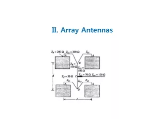
Array of Radiating Elements -Higher Directivity: arrange the radiating elements in space Linear Array Planar Array Conformal Array -Phased Array for Electronically Scanning: change the phase of the exciting current of each element -Element Pattern: Pattern of each radiating element -Array Factor: Pattern of Arrayed isotropic elements
Uniformly Excited, Equally Spaced Linear Array (UE,ESLA) Current amplitudes are all equal
As N increases, the main lobe narrows • As N increases, there are more side lobes: # of SL/period = • Width of minor lobe = half of that of main lobes • As N increases, the side lobe peak decreases • is even function
Main beam maximum direction can be controlled by changing the phase difference between adjacent elements Main Beam Scanning and Beam-width Main Beam Scanning
Visible Region and Radiation pattern
Beam-width 1. BWFN (Beam Width between First Nulls) a) Broad Side:
2. HPBW (Half Power Beam Width) a) Near Broad Side: b) end-fire:
One major lobe at direction Two major lobes at directions Endfire Array 1. The Ordinary Endfire Array One main, and one grating lobe For only one main lobe
2. Hansen-Woodyard Endfire Array To obtain narrower beamwidth than the Ordinary case Visibleregion are not included in Visible Region Optimum phasing and spacing for maximum directivity
Pattern Multiplication Far-zone field of uniform array of identical elements is equal to the product of the field of a single element at a reference point and the array factor of that array Ex) collinear array of short dipoles
Ex) half wave length spaced collinear array of 2 short dipoles
Ex) half wave length spaced parallel array of 2 short dipoles Pattern of short dipole parallel to x-axis E-Plane Pattern H-Plane Pattern
half wave length spaced parallel array of 2 short dipoles E-Plane Pattern 3-D Pattern H-Plane Pattern
Directivity of UE_ESLA Beam Solid Angle Radiated Power Directivity
Beam Solid Angle of UE_ESLA Max. in the visible region for Hansen-Woodyard
Another main lobes appear Directivity is decreased Broadside Case
Broadside Endfire Endfire
Nonuniformly Excited, Equally Spaced Linear Array (NE,ESLA) Array Factor is Z-Transform of Amplitude Distribution and has N-1 Zeros (Pattern Nulls) 1) Uniform Excited
By tapering the current amplitude Tapering toward the ends decrease the side lobe level increase HPBW Tapering toward the center increase the side lobe level decrease HPBW
2) Binomial Distributed 3) Triangular Distributed
Array Pattern Synthesis Fourier Series Method: -.Fourier series expansion of desired array pattern -.Least-mean-square error approximation to the desired pattern
Binomial Arrays: -.Binomial expansion of desired array pattern -.complete absence of side lobes but low directivity
Array Polynomial: • The array factor of an (N+1)-element array is the product of the array of N 2-element arrays superimposed to produce nulls at the zeros of AF • 2. Any polynomial of degree N can be interpreted as an (N+1)-element array • 3. The product of 2 polynomials is the array factor for an array whose pattern is the product of patterns associated with each polynomial by itself
Multi-dimensional Array 2-dimensional Planar Array If the currents separable
Phased Array Scan Principle Beam broadening: scanned off broadside the main beam widens Grating Lobe: if visible region is wider than , there are more than one main lobe For avoiding grating lobes
Feed Networks for Beam Scanning Beam Forming Network Frequency Scanning Parallel Feed (Corporate feed) Parallel-series Feed Electronically phase control