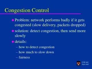
Understanding Multicast Congestion Control Schemes
300 likes | 396 Views
Discover the variations in congestion control strategies for multicast data transmission, like single-rate, multi-rate, window-based, and rate-based approaches. Explore the challenges, benefits, and implementations of these techniques.

Understanding Multicast Congestion Control Schemes
E N D
Presentation Transcript
Congestion control in Multicast ElEG 667 May 7, 2003 by Keyur Shah CIS, University of Delaware
TCP Friendly Congestion Control Schemes Single-rate Multi-rate Window-based Rate-based Window-based Rate-based
Single Rate and Multi Rate • Single Rate : • Data is sent to all receivers at the same rate. • The rate is typically limited by the slowest receiver Thus a single slow receiver can drag down the data rate of the whole group
Multi-rate : • Allows for a more flexible allocation of bandwidth along • different network paths. • Have the ability to generate the same data at different rates over multiple streams. • Receivers try to listen to one or more streams depending on their capacity • Receivers with different needs can be served at a rate closer to their needs
Window-based and Rate-based • Window-based : • uses a congestion window • Each transmitted packet consumes a slot in the congestion window • Acknowledgment of a packet received, frees one slot • Sender is allowed to transmit packets only if a slot is free • Rate-based : • Dynamically adapts the transmission rate according to some network feedback mechanism that indicates congestion
Issues • Single rate multicast congestion control scheme between one sender and one or more receivers • In Multicast, it is typical to use NAKs instead of ACKs to avoid ACK implosion. Also, NAK supression is done so that the Network Elements forward only 1 NAK per group of receivers to the upstream router. • This results in delayed feedback to the sender.
These delays make the system unresponsive to variations in the network conditions. This leads to instability in the network. • Another issue besides Stability…. TCP FRIENDLINESS • Such unresponsive flows which are slow in reacting to • congestion can drive the other competing slow, • responsive flows to a very low throughput
Pragmatic General Multicast Congestion Control (PGMCC)
PGMCC tries to achieve faster response • It also includes positive ACKs • But having each receiver send an ACK causes the scalability problem • Solution: Elect a group representative (called ACKER) who is responsible for sending positive ACKs The ACKER is dynamically selected to be the receiver which would have the lowest throughput Note: Due to the dynamics of the network the receiver with the lowest throughput may change from time to time… i.e. The ACKER will also change.
Window based Controller used by pgmcc • Window based congestion control scheme is run between the sender and the ACKER • Uses AIMD • Uses 2 variables: • Window Size (W) – describes the current window size in packets • Token Count (T) – the no of packets that can be transmitted
On start up or after timeout : W = T =1 • On Transmit : T = T-1 • On ACK reception : W = W + 1/W • T = T + 1 + 1/W On loss detection : W = W/2 • by dupacks • Pgmcc like TCP does some exponential opening of the window (Slow Start). It is limited to a fixed size 4-6 packets • Primarily done to quickly open the window beyond the dupack threshold
ACKER selection • Aim – To determine the receiver which would have the lowest • throughput • Throughput for each receiver can be estimated using • Round Trip Time • Loss Rate Initial ACKER selection When receivers get a data packet with no ACKER selected, all receivers generate a dummy NAK report. The sender will select the source of the first incoming NAK as the new ACKER
Whenever an ACK or NAK arrives from any receiver: • The sender computes the expected throughput (T_i) for that • receiver using the RTT and loss rate. • The sender has already stored the expected throughput for • the current ACKER (T_ACKER) • If T_i < C * T_ACKER • Node i is selected as new ACKER • Note: C is between 0-1, used to avoid too frequent ACKER changes
RTT measurement • Explicit Timestamp : • Transmit a timestamp with every data packet • Receiver echoes the most recent timestamp in the ACK or NAK • Sender computes the RTT by subtracting the received timestamp • from the current value of the clock
Implicit Timestamp : • Record a timestamp for each data packet, but timestamp isn’t transmitted • The receiver reports the most recent sequence no in the ACK or NAK using which the sender can find the corresponding timestamp
Using Sequence numbers : • Least precise technique • Doesn’t require the presence of a high resolution clock on the nodes • Sender doesn’t compute any timestamp • Receiver echoes the most recently received Sequence no • Sender computes RTT as the difference of the most recently sent • Sequence no and the one echoed in the ACK or NAK • Thus RTT is in terms of sequence numbers and not seconds
Timeouts • In TCP, Timeout value is calculated by accumulating statistics of • SRTT and RTTVAR • PGMCC can use a similar scheme, only that whenever the ACKER • changes the computation of SRTT and RTTVAR must be restarted • An ACKER may leave the group without notifying the sender • To avoid many successive timeouts due to absence of an ACKER, • new election of ACKER should be performed after TWO • successive timeouts
non-lossy link Lossy link Intra-protocol fairness with non-lossy and lossy links
non-lossy link Lossy link Inter-protocol fairness
Another Approach • Source based scheme is limited by the slowest receiver • The conflicting bandwidth requirements of all receivers cannot • be simultaneously met with one transmission rate • This can be achieved if we transfer the burden of rate adaption • to the receivers • The source can generate data at different rate over multiple • Streams • The receivers try to listen to one or more streams depending on their capacity.
Receiver driven Layered Multicast (RLM) • The source simply transmits each layer of its signal on a separate • Multicast group • Receiver has the key functionality • It adapts by joining and leaving groups • Conceptually the receiver, • - On congestion, drops a layer • - On spare capacity, adds a layer • Receiver searches for the optimal level of subscription • Similar to TCP which searches for its optimal rate using AIMD
S-R1 path has high capacity - R1 subscribes to all 3 layers and gets highest quality signal R2, R3 have to drop layer 3 because the 512 kb/s link becomes congested
How many layers to subscribe ? Receiver needs to determine whether its current level of subscription is too high or low Too high is easy to find- as it’ll cause congestion Too low – there is no signal to the receiver to indicate that its subscription is too low
Subscribing to layers in RLM RLM performs a join-experinment -spontaneously adds layers at “well chosen” times If a join-experiment causes congestion - the receiver quickly drops the offending layer If a join experiment is successful - the receiver is one step closer to the optimal operating point
Join experiments cause transient congestion • Need to minimize the frequency and duration of the join experiments • Solution : A learning strategy • Doing join experiments infrequently when they are likely to fail • And doing them readily when they are likely to succeed • Done by, • managing a separate Join Timer for each level of subscription
4 C 3 D E B F 2 A 1 Layer # Time
Scalability of RLM • If each receiver carries out the adaptation algorithm • The system scales poorly • As the session membership grows • Aggregate frequency of join experiments increases • network congestion increases
Also, join-experiments can interfere with each other R1 R2 Join-2 Join-4 S congestion R1 can misinterpret the congestion and back off layer 2 join-timer
Solution – Shared Learning Receiver notifies the entire group, that it is now performing a join-experiment on layer ‘x’ All receivers can learn from the failed join experiments of other receivers