Download
1 / 29
290 likes | 375 Views
Learn how NTX system achieves small beam spot sizes for heavy ion inertial fusion, addressing key driver requirements and experimental achievements. Explore the impact of plasma plug and volume plasma on beam neutralization.

E N D
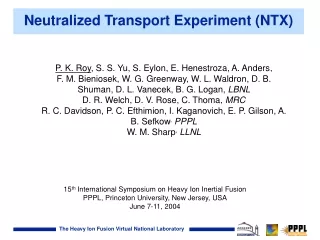
Neutralized Transport Experiment (NTX) P. K. Roy, S. S. Yu, S. Eylon, E. Henestroza, A. Anders, F. M. Bieniosek, W. G. Greenway, W. L. Waldron, D. B. Shuman, D. L. Vanecek, B. G. Logan, LBNL D. R. Welch, D. V. Rose, C. Thoma, MRC R. C. Davidson, P. C. Efthimion, I. Kaganovich, E. P. Gilson, A. B. Sefkow,PPPL W. M. Sharp,LLNL 15th International Symposium on Heavy Ion Inertial Fusion PPPL, Princeton University, New Jersey, USA June 7-11, 2004
Overview ● Requirements of NTX for Driver ● NTX system and diagnostics ● Keys to a small spot ● Experimental results of neutralization. ● Sensitivity study ● Achievements/conclusion
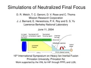
The HIF Driver Requires Beam Neutralization in Chamber Transport to Hit mm-sized Spot on Target Driver needs: ●Present generation of drivers requires total of ~40 kA divided between perhaps hundred beams, each beam of 2 mm focal spot radius. How and what Neutralized Chamber Transport can do: ●Electrons from external source are entrained by the beam and neutralize the space charge sufficiently that the pulse focuses on the target in a nearly ballistic manner for a small spot.
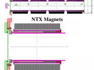
Final Focus Chamber Transport Neutralized Transport Experiment (NTX) Addresses Driver-Relevant Issues ●Perveance is the key parameter for final focus and neutralization ●NTX covers range of perveance relevant to the driver (K≤10-3). A schematic of the NTX beam line setup
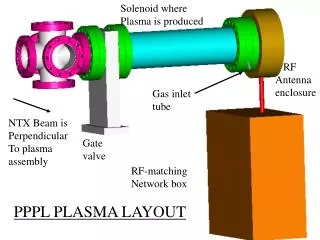
Gated Camera NTX System Setup and diagnostics Located at LBNL
Keys to a Small Spot ●Low source emittance ●Optimal convergence angle Source of emittance growth: ●Geometric Aberration ●Magnetic transport mismatch ●Efficient neutralization —plasma plug —volume plasma
Extraction of Uniform High Brightness Beam from NTX Injector Increased Source Temperature (~185W) Aperturing Smooth source surface Unapertured beam Lower Temperature source (~160w) Uneven source
Aperturing for High-brightness and High Perveance beam Designed by EGN code NTX beam scraper system EGN simulation of NTX diode &beam aperture
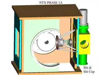
NTX Provides low emittance beam (300kV, 25 mA, 2-cm aperture). Slit-integrated density profile and (x, x’) phase space of a high-brightness apertured beam (300kV, 25 mA, 2-cm aperture).
Final Focus Chamber Transport Magnetic Final Focus Transport ●Perveance is the key parameter for final focus and neutralization ●NTX covers range of perveance relevant to the driver (K≤10-3). A schematic of the NTX beam line setup
265 keV 283 keV 191keV 401keV Good agreement between Experimental and Theoretical Beam profile at Entrance of Final Drift Section Simulation Experiment (1.5 mA beam, 5 mm initial radius, Ne ~ 1.2x10¹¹/cm3, 20mm-20mr)
Measured and Calculated Beam Profiles Agreed Well Horizontal density profile 265keV Vertical Horizontal 283keV Vertical
Typical NTX Ion Beam is Focused to the Final Drift Section for Neutralization (24 mA Beam Current) Experimental results and simulations of NTX beam profile and phase-space distribution at exit of channel
LSP predicted Neutralized Reduces Beam Spot No neutralization 1.5 cm 300 keV, 25 mA, 0.1 pi-mm-mrad, K+ beam Plasma Plug 1.4 mm Plasma Plug + Volume 1 mm
Phase II Phase I Phase III 6 inch pipe 3 inch pipe Unwanted neutralization for “vacuum” propagation in small pipe Unexpected Partial Beam Neutralization in the Final Drift Section was controlled by a Radial Bias Mesh Radial mesh suppresses beam- Generated secondary electron Electron current collected in the radial mesh
Simulation Experiment 6 inch pipe Experiment 3 inch pipe Mesh (+1kV) 260 – 300keV Electron Suppression provided beam for controlled Neutralization
MEVVA plug RF Plasma system MEVVA Plasma Plug and RF Volume Plasma Source Neutralized Ion Beam for Small Spot Size a) b) c) Neutralization drift section
High Density Plasma Obtained from MEVVA Plasma plug and RF Plasma (~1011 cm-3) Each point on the IV characteristic for MEVVA plug. The ion saturation current is used for plasma density. Neutral Pressure and RF Plasma Density Argon Plasma 3.7<t<4.0mS N>1011 cm-3 P<10-5 Torr Density ~1011 cm-3
Non-neutralized transport Effect of plasma plug on spot size Effect of plasma plug and volume plasma on spot size FWHM: 2.14 mm FWHM: 2.71 cm FWHM: 2.83 mm Reduction of Spot Size Using Plasma Plug & Volume Plasma (24 mA beam, 20 mm initial radius)
100% Current Transmission Through Neutralized Drift Section (24 mA Beam)
Pinhole scan at Entrance to Neutralization* and Neutralized beam (6 mA beam, Ne ~ 2x10¹¹/cm3) Full 2-D Pinhole Scan Vertical Pinhole Scan rms size ~ 1.0 mm 7 mm Neutralized beam Plasma density ~ 2x10¹¹/cm3 Movable Pinhole Measurements of 4-D Phase Space rms size ~ 1.4 mm *Image taken after pinhole sample has drifted 1 meter
Beam profile at focal plane for three neutralization methods(6 mA beam, 10mm initial radius) MEASUREMENT With plasma plug and RF Plasma Fluence With plasma plug 100% neutralization 100% neutralized MEVVA and RF MEVVA ONLY SIMULATIONS 100% neutralized MEVVA and RF MEVVA ONLY
Sensitivity Study: Beam Spot Size Dependency on Convergence Angle Non neutralized beam radius as a function of convergence angle calculated using WARP code Measured neutralized beam radius as a function of convergence angle at the end of final focus
Sensitivity Study of Neutralization Beam envelope variation with axial position Beam envelope variation with plasma discharge voltage Variation with beam energy Head to tail variation
Summary ●We have completed a detailed study of neutralized final transport. ● The experimental results are in good agreement with simulations. ● The NTX experiments have significantly increased our confidence for a variable driver final focused scenario.