Download
1 / 26
260 likes | 340 Views
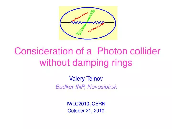
Consideration of a Photon collider without damping rings. Valery Telnov Budker INP, Novosibirsk IWLC2010, CERN October 21, 2010. Contents. Introduction Factors determining γγ luminosity Present limit on γγ luminosity (with beams from DRs) Role of the electron beam polarization

E N D
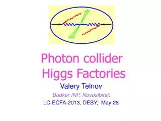
Consideration of a Photon collider without damping rings Valery Telnov Budker INP, Novosibirsk IWLC2010, CERN October 21, 2010
Contents Introduction Factors determining γγluminosity Present limit on γγluminosity (with beams from DRs) Role of the electron beam polarization Emittances of beams from RF-guns Combining of low charge, low emittance bunches from RF guns in longitudinal phase space (using energy difference). A high luminosity photon collider based on RF-guns (unpolarized and polarized). Discussion-conclusion Valery Telnov
b~γσy~1 mm αc~25 mrad ωmax~0.8 E0 Wγγ, max ~ 0.8·2E0 Wγe, max ~ 0.9·2E0 Valery Telnov
Factors limiting γγ,γe luminosities Telnov,1998 (ILC) • Collision effects: • Coherent pair creation (γγ) • Beamstrahlung (γe) • Beam-beam repulsion (γe) • On the right figure: • the dependence of γγandγe luminosities in the high energy peak vs the horizontal beam size (σy is fixed). At the ILC nominal parameters of electron beams σx ~ 300 nm is available at 2E0=500 GeV. Having beams with smaller emittances one could obtain much higher γγluminosity. Physics does not forbid an increase of the γγluminosity by a factor of 30. γe luminosity in the high energy peak is limited by beamstrahlung and beam repulsion. So, one needs:εnx, εny as small as possible and βx , βy ~ σz Valery Telnov
Realistic luminosity spectra ( and e) (decomposed in two states of Jz) (ILC) Usually a luminosity at the photon collider is defined as the luminosity in the high energy peak, z>0.8zm. For the nominal RDR ILC beams (from DRs) Lγγ(z>0.8zm) ~0.17Le+e-(nom) (but cross sections in γγ are larger by one order!) Due to chromo-geometric aberrations the minimum βx~4mm (A.Seryi), (while βy~σz~0.3-0.4 mm) In the general case, at the ILC Lγγ(z>0.8zm) ~0.1Le-e-geom) (not valid for multi-TeV colliders with short beams(CLIC) due to coherent e+e- creation) Valery Telnov
Importance of the electron polarization The electron polarization increases the number of high energy photons nearly by factor of 2). Valery Telnov
Ideal luminosity distributions, monohromatization (ae is the radius of the electron beam at the IP, b is the CP-IP distance) Electron polarization increases the γγluminosity in the high energy peak up to a factor of ~3-4 (at large x). Valery Telnov
Highest energy scattered photons are polarized even at λe=0 (see (b)) The electron polarization makes the region with a high polarization (at ω~ωm) wider (compare a and b). Valery Telnov
Realistic luminosity spectra at the PLC (2λe=0.85) ILC- γγluminosity with J=2 is smaller than that with J=0 by factor of 10-20 (that is very important for extraction of the Higgs(130) Valery Telnov
Comparizon of transverse emittances in damping rings and photo-guns The ILC DR (polarized):εnx=10-3 cm, εny=3.6·10-6 cm, βx~4 mm RF guns (3 nC, unpolarized): εnx=3·10-4 cm, εny=3·10-4 cm, βx~2 mm DC guns (polarized): εnx=7·10-3 cm, εny=7·10-3 cm, βx~4 mm Lgeom~ F(pol.ench.)/(εnxεnyβxβy)1/2 Fpol.ench~2-3.5(depends on the energy) Very approximately with account of βx variation (chromo-geom.aberrations): L(DR)/ L(RFguns,unpol)~ 7-12 L(DR)/ L(DCguns,pol) ~ 100 Therefore until now DRs were considered as a preferable source of electrons for the PLC. Methods of additional cooling electrons after guns or DR was suggested (laser cooling), but it is very difficult. Valery Telnov
What to do? First of all, it is necessary to develop polarized RF guns with low emittances. If their emittances will be determined by space charge effects (as in unpolarized RF-guns) L(DR)/ L(RFguns,unpol)~ 3 This is better, but still the luminosity is higher with DRs, new ideas are needed. Valery Telnov
Longitudinal emittances Let us compare longitudinal emittances needed for ILC with those in RF guns. At the ILCσE/E~0.3% at the IP (needed for focusing to the IP), the bunch length σz~0.03 cm, Emin ~75 GeV that gives the required normalized emittance εnz(σE/mc2)σz~15 cm In RF gunsσz~0.1 cm (example) and σE~ 10 keV, thatgives εnz~2·10-3 cm, or 7500 times smaller than required for ILC! So, photoguns have much smaller longitudinal emittances than it is needed for linear collider (both e+e- or γγ). How can we use this fact? Valery Telnov
A proposed method Let us combine many low charge, low emittance beams from photo-guns to one bunch using some differences in their energies. The longitudinal emittance increases approximately proportionally to the number of combined bunches while the transverse emittance (which is most important) remains almost constant. It is assumed that at the ILC initial micro bunches with small emittances are produced as trains by one photo gun. In the CLIC case the distance between bunches is very small therefore micro bunches are produced by many separate photo-guns. Each gun is followed by round-to-flat transformer (RFT). RFT does not change the product of transverse emittances, but it is easier to conserve emittances manipulating with flat beams in the horizontal plane. Below the scheme for the ILC case is considered. Valery Telnov
Round to flat transformer (RFT) In 1998 Ya. Derbenev has found that using the RF gun inside the solenoid and following skew quadrupoles one can transform a round beam (from an electron gun) to a flat beam with an arbitrary aspect ratio. After such transformation εnxεny=ε0nxε0ny=(εGn)2=const (at εnx.>>εny) The ratio R=100 was demonstrated at FNAL and this is not the limit. The initial goal of the R-F-transformer was the e+e- linear collider, but now there are much wider applications. Valery Telnov
Scheme of combining one bunch from the bunch train (for ILC) (64→1) Valery Telnov
Description of the scheme After the gun and RFT the train passes several stages of deflectors-combiners. Each two adjacent bunches are redirected by the deflector (D) (transverse RF-cavity) into two beamlines which have difference in length equal to distance between bunches. One of these beamlines contains a weak RF-cavity which adds ΔE to the beam energy. Further these two beams are combined in a dispersion region of the combiner (C) using the difference in beam energies. In order to combine the whole train to one bunch the procedure is repeated m=log2 nb times. The scheme shown above assumes nb=64, that needs 6 stages. The energy between stages is increased by linacs in order to avoid emittance dilution due to the space charge effects. At the end, the final bunch is compressed down to required bunch length by a standard bunch compressor. Valery Telnov
Choice of ΔEi In principle, one can combine the final bunch in a such way that sub-bunches are spaced in energy equidistantly and the total energy spread is ΔEtot=nb-1ΔE1, where ΔE1 is the energy several times larger than σE in the sub-bunch. However, it is difficult to combine two beams with very small energy gap. Sub-beams have natural transverse sizes associated with their emittances, the distance between two sub-beams in the combining region should be larger than these beam sizes. Smaller energy gap means larger dispersion in the combining region. Larger dispersion means larger bending angles and larger distances that may be problematic for final stages with high energies. Therefore ΔEn shouldincrease with the stage number in order to make easier technical problems. It is important only that ΔE1 is several times larger than the initial sub-beam energy spread and the final longitudinal emittance satisfies the ILC requirement. Valery Telnov
Choice of ΔEi (continue) For example, let us require the gap between two combining beams at the stage n ΔEn =ETn-1 , where ETn is the total energy spread at the stage n, then ETn=3n-1ΔE1. If ΔE1=40 keV at E~50-100 MeV then ET6=9.7 MeV at E~1 GeV. After the bunch compression at E~2-3 GeV by a factor of 3 the energy spread will be about σE~10 MeV (σE/E=10-4 at E=100 GeV), that is better than necessary. Valery Telnov
Bunch length during beam combining In order to decrease space charge effects (for transverse emittance)bunches should be as long as possible, however for long bunches RF-acceleration induces the longitudinal emittance A reasonable choice σz~1-1.5 mm for λ~20 cm. If necessary, RF induced longitudinal emittance can be canceled by deceleration in cavities with 2 (or 4) times shorter wavelength. After beam combining the final bunch is compressed by a facor of 3 down to the required bunch length (σz=0.4 mm for ILC). Valery Telnov
Emittances in RF-guns • There are two main contribution to transverse emittances in RF guns: • Space charge induced normalize emittance; • Thermal emittance. • The space charge emittance εsc~10-4 Q[nC] cm • The thermal emittance εth~0.5·10-4R[mm], cm • Assuming R2Q and R=1 mm at 1 nC, we get for Q=3/64 nC • εsc~0.5·10-5 cm, εth~10-5 • →εn, tot ~10-5 cm • After RFT with the ratio 100 • εnx~10-4 cm, εny~10-6 cm. Valery Telnov
Luminosities Beam parameters: N=2·1010 (Q~3 nC), σz=0.4 mm Damping rings(RDR): εnx=10-3 cm, εny=3.6·10-6 cm, βx=0.4 cm, βy=0.04 cm, RF-gun (Q=3/64 nC) εnx~10-4 cm, εny=10-6 cm, βx=0.1 cm, βy=0.04 cm, The ratio of geometric luminosities LRFgun/LDR=12~10 So, with polarized RF-guns one can get the luminosity ~10 times higherthan with DR. In the case of unpolarized RF-guns the effective luminosity will behigher than with DR by a factor of 3-4. Valery Telnov
Comparison of polarized and unpolarized beams =(b/γ)/σy The following cases are considered: polarized 85%, =3 2E=200 GeV, x=1.8 unpolarized, =3 polarized 85%, =3 2E=500 GeV, x=4.5 unpolarized, =3 Laser photons have 100% helicity in all examples. • To see better the luminosity with central collisions a cut • on the parameter R=|ω1-ω2|/‹ω› is applied. • The increased CP-IP distance b is used in order to suppress low Wγγ luminosity (the case =3). Valery Telnov
Comparison of polarized and unpolarized electron beams, 2E=200 GeV, =3 at z>0.85zm Lp0/Lp2~20 polarized e zoom Lup0/Lup2~3.55 zoom unpolarized e Lp0/Lup0=2.2 and L0/L2 suppression is higher 20/3.5=5.7 times for pol. beams. Nevertheless, γγ collisions with unpol. electrons have rather good polarization properties, sufficient for study of many processes. Valery Telnov
Comparison of polarized and unpolarized electron beams 2E=500,=3 at z>0.85zm zoom Lp0/Lp2~20 zoom Lup0/Lup2~2.5 Lp0/Lup0=3.3 and L0/L2 suppression is higher 20/2.5=8 times for pol. beams. Valery Telnov
Discussion, conclusion • Polarized RF-guns • Having polarized RF guns with emittances similar to existing unpolarized • guns we could obtain the γγluminosity ~10 times higher than that with ILC • DRs (all polarization characteristics are similar). • Unpolarized RF-guns • Already with existing RF guns we can dream on the γγ luminosity higher • than with DR by a factor of 10/Fpol.ench.., where Fp.e.~2.2-3.3 for 2E=200- • 500 GeV. The γγluminosity will be about ~3-4 times higher than with DR, • but L0/L2 in the high energy peak will be only 3.5-2.5 instead of 20 for • polarized beams, which is acceptable (the case of H(120) should be • checked). • Possible technical problems in suggested technique • Dilution of the emittance due to wakefields in combiner sections. • All parameters of beamlines should be continuously adjusted in order to combine all 64 bunches to the same phase space (except energy). • The above dreams should be proved by realistic consideration-optimization. Valery Telnov