Development of Ultrasonic Volumetric Flow Sensor for Gas Measurement in Thermal Systems
This project focuses on creating an ultrasonic volumetric flow sensor capable of accurately measuring the volume of gas flowing through a combustion chamber for a Thermal Abatement System. The objectives include demonstrating the functionality of ultrasonic technology in a working sensor, addressing design criteria, and utilizing a stainless-steel housing with provisions for electrical connections. Initial evaluations have been conducted on flow properties and pressure drop, with promising results indicating that flow ranges from laminar to transitional turbulent. Future considerations include improving thermal insulation and addressing existing electrical challenges.


Development of Ultrasonic Volumetric Flow Sensor for Gas Measurement in Thermal Systems
E N D
Presentation Transcript
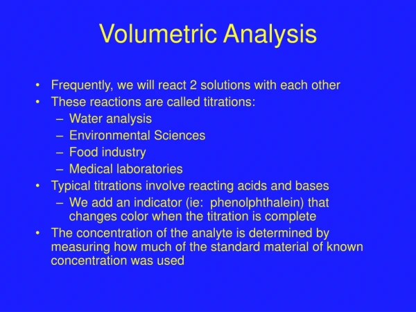
Volumetric Flow Sensor Group Project Summary
Mission Statement • To develop a Volumetric Flow Sensor to measure the volume of gas flowing through a quadrant and into the combustion chamber of the Thermal Abatement System.
New Project Objective • Be able to demonstrate the ability to prove that Ultrasonic Technology works with a working sensor • Temperature design criteria to be ignored due to “lead time” of transducers that existed.
Sensor Housing Assembly • Based of standard vacuum seal flange assemblies • Uses a combination of standard and non-standard parts • Components made of 316L 304 stainless steel
Circuit Box • Made of Stainless Steel, prototype design • Has provisions for RS-232, Power Switch, Power Input, BNC, LCD display, and cooling fan and vents
Flow properties • Reynolds number • minimum – 442 – maximum – 4416 • Conclusion is that flow ranges from laminar to transitional turbulent flow • Flow is ‘semi-normal’ due to the oxygen inlet and transducer cavities
Evaluation – Pressure Drop • Differential Pressure meter used to measure pressure drop • ‘Rotameter’ flow meter used to measure flow
Results – Pressure Drop • Pressure marginal, which was what was expected • Design condition of minimal pressure drop met
Future Design Considerations • Proposed Transducer Sleeve to be made from PEEK plastic • Sleeve will insulate radiating heat from Quadrant and Welded fitting • Could be custom made by a transducer company, lead time 6+ months • FEA model shows that upper most temperature would 70 C
Main Electrical Design • This is the main PCB circuit schematic. • MC and TDC had a few connection errors • The analog switch IC’s do not function properly • The DC transformer circuit does not function properly • Significant modifications were made to the PCB.
7-Segment Electrical Design • This circuit was straight forward, but design was put off due to the design of the electrical box and the main circuit. It functions properly, however new 7-segment displays will need to be purchased.
Electrical Results • Complications: • High voltage DC transformer circuit does not work properly. • Due to the low current on the primary side not causing a large enough voltage drop across the primary inductor. Higher current will be needed to produce 200+V on the secondary. • Analog switch IC’s do not work properly. • We are unsure as to why they were not working. We removed one from the PCB and tested it, it was working exactly as it should. The only difference is the resistors in the circuit, but we do not think that should have an adverse effect on the performance of the switches. • Being that those two circuits don’t work, we were not able to test anything beyond that point. What wasn’t tested is: • Time-of-flight of the pulse • Whether the transducer would send and be able to receive within the walls of the pipe (due to not having the voltage required) • Flow measurement and display of that flow (the display does work, however) • The receiving circuitry was not tested.
What Do You Think? • Comments • Questions • Concerns