Download
1 / 17
170 likes | 187 Views
Analyzing current topology near auroral arcs using FAST data in conjunction with optical observations. Discovering unique configurations and areas for further research.

E N D
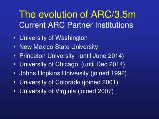
3D Current Topology in the Vicinity of an Evening Arc O. Marghitu (1,3), G. Haerendel (2), B.Klecker (3), and J.P. McFadden (4) • Institute for Space Sciences, Bucharest, Romania • International University of Bremen, Germany • Max-Planck-Inst. f. extraterr. Physik, Garching, Germany • Space Sciences Lab., Univ. of California at Berkeley, US EGS-AGU-EUG, Nice, April 9, 2003 Credit: Jan Curtis, http://climate.gi.alaska.edu/Curtis
Acknowledgement C. Carlson – FAST R. Ergun – FAST Electric field R. Strangeway – FAST Magnetic field FAST Team J. Vogt, H. Frey – Optical data World Data Center for Geomagnetism, Kyoto – AE Index
Contents • Experimental setup: FAST and ground based optics • Data: Optical and FASTmeasurements • Current topology • Summary • Prospects
Setup: Ground Optics • Low-light CCD cameras developed at MPE, Garching • Wide-angle optics (86ox64o) • Pass band filter • Exposure time 40 ms multiplied with powers of 2 • Digitized images, 768x576x8 • Location: Deadhorse, Alaska, 70.22o LAT, 211.61o LON • Time: Feb. 9, 1997, 8:22UT Photo: courtesy W. Lieb, MPE
Setup: FAST • 2nd NASA SMEX Mission • PI Institution UCB/SSL • Launch: August 21, 1996 • Lifetime: 1 year nominal; still operational • Orbit: 351 x 4175km, 83o • Spin axis perpendicular to the orbit plane • Electric field: three orthogonal boom pairs equipped with spherical probes • Magnetic field: a DC fluxgate and an AC search coil • Mass spectrometry: TEAMS – measures full H+ and O+ distributions in ½ spin and He+ in one spin • Plasma analyzers: IESA, EESA, SESA – high time resolution electron and ion data, with uninterrupted 360o coverage http://www-ssc.igpp.ucla.edu/fast
Data: AE index, Feb. 9, 1997 http://swdcdb.kugi.kyoto-u.ac.jp
Optical Data: 8 min N E Selection of images, 1 min apart, taken at UT 8:18 – 8:26. FAST crosses the camera´s FoV in the frames 4, 5, 6; the satellite´s ionospheric footprint is shown as a square. The limits of the ion beams detected by FAST are overlaid in all the frames, to provide a reference.
Optical Data: 1 min Images 4 s apart during 8:22-8:23. FAST footprint is shown as a square. ´11´ and ´22´ are the limits of the first two ion beams. The arc is stable and drifts with ~200m/s, equivalent to ~10mV/m (assuming the arc has no proper motion).
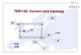
FAST Data: Trajectory Magnetic noon at the top N=magnetic pole X=arc FAST Path Auroral Oval Terminator at 110km
FAST Data: Large Scale Top: Potential. Middle: Magnetic field in the Satellite Associated System (SAS). Bottom: Magnetic field in the Arc Associated System (AAS).
FAST Data: Medium Scale Panel 1: Magnetic field. Panels 2-4: Electrons, energy. Panel 5: Electrons, p.-a. Panels 6: Ions, energy Panels 7: Ions, p.-a. Panel 8: Electric potential The arc is north of the convection reversal
Current Configuration: FR vs. CR The relative positions of the FAC reversal (FR), the convection reversal (CR), and the arc. The CR is very close to the FR and just a negligible fraction of the downward FAC returns to the magnetosphere as upward FAC.
Current Configuration: Flow Topology Type 1 Type 2 From Bostrom (1964) Current Electric field Plasma convection
Current config: quantitative evaluation Conductance from particle precipitation + • Electric field • High-altitude data cannot be mapped to ionosphere when FAST crosses the AAR • FAST does not measure the E–W electric field • Method based on a parametric model of the arc, prezented in the poster session. In order to obtain consistent results one has to take into account, as a minimum: • Ionospheric polarization => Exnot const. => a1 , ..... , an • Hall current perpendicular to the arc => Ehnot 0 => b0 • Coupling FAC – electrojet => Jhnot divergence free => c1 Current
Current config: quantitative evaluation Jx , Jh, J||
Summary • Because of the close proximity of the CR and FR the downward and upward FACs appear to be electrically separated in the ionosphere. • The current continuity is achieved at the expense of the electrojets. • Although the magnetic field data suggests the standard Bostrom Type 2 (1B2) configuration, the current topology looks like 2 times Bostrom Type 1 (2B1)
Prospects • Check the current topology for other orbits. First step: the relative positions of FR and CR. • Investigate the conditions under which the 1B2 topology develops. • Check the results with ground observations, when conjugated data exists.