Download
1 / 42
430 likes | 636 Views
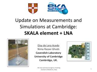
Update on Measurements and Simulations at Cambridge: SKALA element + LNA. Eloy de Lera Acedo Nima Razavi Ghods Cavendish Laboratory University of Cambridge Cambridge, UK. Overview. Design and Simulations Measurements Impedance and coupling (AAVS0 array) Pattern LNA

E N D
Update on Measurements and Simulations at Cambridge:SKALA element + LNA Eloy de LeraAcedo NimaRazaviGhods Cavendish Laboratory University of Cambridge Cambridge, UK. AA-low technical progress meeting 23/10/12 Medicina, Italy
Overview • Design and Simulations • Measurements • Impedance and coupling (AAVS0 array) • Pattern • LNA • Future work and conclusions • SKALA with integrated ground plane • Cross-polarization
Design • Dual-polarization from (50) 70-450 (600) MHz • Element gain ~ 7dB • Receiver noise < 35 K above 100 MHz • Receiver gain > 36 dB (2 stages)
Design and Simulations • The antenna was designed using CST • The simulations of the element were confirmed using HFSS • The MoM/MBF specialized code (UCL/UCAM) was used to verify the behaviour at array level (SKA stations) • Mutual coupling analysis (averages out for random configurations) • Low order models for calibration Objective of the measurement campaign with single elements and the AAVS0 array: Confirm that these simulations are correct. We design the SKA with simulations!
EM characterization of SKA arrays • Mutual coupling effects randomize out in quasi-random configurations.** *Gonzalez-Ovejero, D., De LeraAcedo, E., Razavi-Ghods, N., and Craeye, C. (2009) *Gonzalez-Ovejero, D., De LeraAcedo, E., Razavi-Ghods, N., Garcia, E., and Craeye, C. (2011)
EM characterization of SKA arrays • Accurate EM simulations can be useful for the telescope calibration.** + = Q=3 *De LeraAcedo, E., Razavi-Ghods, N., Gonzalez-Ovejero, D., Sarkis, R., and Craeye, C. (2011) **Craeye, C., Gonzalez-Ovejero, D., Razavi-Ghods, N., and de LeraAcedo, E. (2012)
EM characterization of SKA arrays • The method has been tested before.* Measurements Simulations MoM Simulations MBF *Raucy, C., De LeraAcedo, E., Craeye, C., Gonzalez-Ovejero, D., and Razavi-Ghods, N. (2012)
EM characterization of SKA arrays: Antenna model in simulations CST MoM spine
Design and Simulations Pattern Effective aperture • Important for a SKA antenna element (embedded in a station) Noise (sky, ground, LNA) Antenna impedance Calibratability Cross-polarization LNA noise & gain Linearity, stability, ripple Sensitivity LNA intermodulation Element’s footprint Cost (including deployment and durability) LNA power consumption Power consumption Materials, construction, assembly, maintenance, etc. Material properties
Design and Simulations • Sensitivity (“Antenna Standardization report”: ShantanuPadhi, Ver: 2.0, 1 August 2012) ~1,300 m^2/K for 500,000 elements
Measurements Pattern Effective aperture • We can measure most of what we can simulate Noise (sky, ground, LNA) Antenna impedance Calibratability Cross-polarization LNA noise & gain Linearity, stability, ripple Sensitivity LNA intermodulation Element’s footprint Cost (including deployment and durability) LNA power consumption Power consumption Materials, construction, assembly, maintenance, etc. Material properties • *See more about future measurements in Nima’stalk (test plan)
Measurements: Impedance and coupling tests • Scaled prototype Zdiff - + 1 2 VNA
Measurements: Impedance and coupling tests MoM CST • SKALA element Test board
Measurements: Impedance and coupling tests SKALA element
Measurements: Impedance and coupling tests *B. Fiorelli
Measurements: Impedance and coupling tests 2 SKALA elements 1.5 m apart • AAVS0 array
TOP VIEW 1.5 m Measurements: Impedance and coupling tests
Measurements: Impedance and coupling tests • Common-mode currents (with Howard Reader – April 2012)
Measurements: Pattern • Scaled prototype: • Direct line of sight range (main reflected ray absorbed). • Using Spectrum analyser, signal generator and power combiner. • At Lords Bridge. Easy, quick and great results.
Measurements: Pattern • SKALA element (at QinetiQ) • Arch above antenna (near field). • Ground refection range.
Measurements: Pattern E-plane cut
Measurements: Pattern 200 MHz H-plane cut
Measurements: Pattern • SKALA element (with Howard Reader) • At Stellenbosch University. • Ground refection range. www.paardefontein.co.za
Measurements: Pattern • Near field pattern measurement (AAVS0)
Measurements: LNA • Concept LNA1 COAX LNA2
LNA Transformer • Design 2nd stage amplifier AVAGO MGA-16516
LNA • Simulations
Measurements: LNA • Gain
Measurements: LNA • Hot/cold measurement with 150 Ω load. • Liquid Nitrogen (77 K) • Room temperature (290 K) • Filtering
Measurements: LNA • 1st stage amplifier with Agilent noise analyser in reverberation chamber.
Measurements: LNA • Noise tuner and noise parameter measurement in reverberation chamber at ASTRON.
Measurements: LNA • Intermodulation • Not great expectations (by design): • OIP2: 17 dBm • OIP3: 19 dBm • Others: • Tests on single transistors. • Connection to antenna and noise measurement in reverberation chamber. • RFI monitoring.
Future work and conclusions • SKALA with integrated ground plane
Future work and conclusions • Cross-polarization (“IXR SKALA with GP vs Vivaldi V2 with Soil C”, 08/10/2012 – B. Fiorelli)
Future work and conclusions • Most measurements already done. • The performance is looking like the simulations said. • Element • LNA • More measurements to be done, using a back-end (see Nima’s talk). • More development coming. • Even cheaper element, long lasting materials, integrated ground plane. • Lower power consumption for LNA, better IP2/3.
Lord’s Bridge Observatory SKALA-AAVS0