Sybex CCNA 640-802 Chapter 6: IP Routing
Sybex CCNA 640-802 Chapter 6: IP Routing. Chapter 6 Objectives. Understanding IP routing Static routing Default routing Dynamic routing RIP RIPv2 IGRP Verifying routing

Sybex CCNA 640-802 Chapter 6: IP Routing
E N D
Presentation Transcript
Sybex CCNA 640-802 Chapter 6: IP Routing
Chapter 6 Objectives • Understanding IP routing • Static routing • Default routing • Dynamic routing • RIP • RIPv2 • IGRP • Verifying routing • [Oddly, the exam topics covered in this chapter (6) are listed at the beginning of the chapter. Some of the topics listed are not really covered in this chapter at all. For example, OSPF and EIGRP are covered in chapter 7, not chapter 6. ] 2
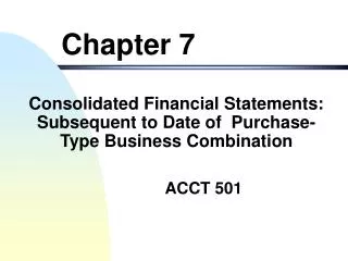
In order to “route”, a router needs to know: Remote Networks Neighbor Routers All Possible routes to remote network The absolute best routeto all remote networks Maintain and verify the routing information Remember: a router does not deal with hosts! A router only deals with networks, and the best path to them An IP address allows packets to move from network to network Hardware (Mac) addresses move the packets to specific hosts What is Routing? A D C B
Basic Path Selection On what interface will the router send out a packet if it has destination address of 10.10.10.18?
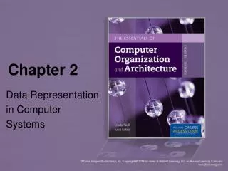
Simple IP Routing >ping 172.16.1.2 172.16.2.0 172.16.1.0 172.16.3.1 172.16.3.2 e0 e0 s0 A B B s0 172.16.2.2 Host A 172.16.1.1 172.16.2.1 172.16.1.2 Host B
Routing/PDU Example:Host A Web browses to the HTTP Server…. 1. The destination address of a frame will be the: Host A address 2. The destination IP address of a packet will be the IP address of the: Destination Router 3. The destination port number in a segment header will have a value of 80 (the port number used by HTTP)
Idea of routing (5 guest slides) • Routers forward datagrams between connected networks • They need to know via which interfaceto send a datagram • Routing decisions are based on the information stored in the routing table
Routing table • Tells where to send datagram for a particular network NetworkNext-HopPortMetric 194.181.200.0 194.181.208.1 Eth0 1 193.2.1.0 194.181.208.320 Eth1 14 153.5.0.0 194.181.214.25 Fddi0 8 0.0.0.0 194.181.210.1 S0 5 • “Next-Hop” routers must be directly reachable
Routing table (cont.) • Default Route - a special entry in the routing table: • “Pass all datagrams for unknown networks to this router” • Represented by the entry for network 0.0.0.0 • Routing uses networkpart of the address!
Step-by-Step: IP Routing Process (book, pp 331-36) • The IP routing process is fairly simple and doesn’t change, regardless of the size of your network. • For an example, we’ll use Figure 6.2 to describe step-by-step what happens when Host_A wants to communicate with Host_B on a different network
Step 1 • Internet Control Message Protocol (ICMP) creates an “echo request” payload (which is just the alphabet in the data field). • The echo request is the first part/half of what is commonly called a “Ping”; the second part is the echo reply, from the device being “pinged”. • [So, A is going to “ping” B]
Step 2 • ICMP hands that payload to Internet Protocol (IP), which then creates a packet. • At a minimum, this packet contains an IP source address, an IP destination address, and a Protocol field with 01h. • (Remember that Cisco likes to use 0x in front of hex characters, so this could look like 0x01.) • All of that tells the receiving host to whom it should hand the payload when the destination is reached—in this example, ICMP.
Step 3 • Once the packet is created, IP determines whether the destination IP address is on the local network or a remote one.
Step 4 • Since IP determines that this is a remote request, the packet needs to be sent to the default gateway so the packet can be routed to the remote network. • The Registry in Windows is “parsed” to find the configured default gateway.
Step 5 • The default gateway of host 172.16.10.2 (Host_A) is configured to 172.16.10.1. For this packet to be sent to the default gateway, the hardware address of the router’s interface Ethernet 0 (configured with the IP address of 172.16.10.1) must be known. • Why? So the packet can be handed down to the Data Link layer, framed, and sent to the router’s interface that’s connected to the 172.16.10.0 network. • Because hosts only communicate via hardware addresses on the local LAN, it’s important to recognize that for Host_A to communicate to Host_B, it has to send packets to the Media Access Control (MAC) address of the default gateway.
Step 6 • Next, the Address Resolution Protocol (ARP) cache of the host is checked to see if the IP address of the default gateway has already been resolved to a hardware address. Two possibilities ensue: • 1. If it has, the packet is then free to be handed to the Data Link layer for framing. (The hardware destination address is also handed down with that packet.) To view the ARP cacheon your host, use the following command: • C:\>arp -a • Interface: 172.16.10.2 --- 0x3 • Internet Address Physical Address Type • 172.16.10.1 00-15-05-06-31-b0 dynamic • 2. If the hardware address isn’t already in the ARP cache of the host, an ARP broadcastis sent out onto the local network to search for the hardware address of 172.16.10.1. The router responds to the request and provides the hardware address of Ethernet 0, and the host caches this address.
Once the packet and destination hardware address are handed to the Data Link layer, the LAN driver is used to provide media access via the type of LAN being used (in this example, Ethernet). ALAN driver provides communication control between the NOS and NIC (network interface card). • A frame is then generated, encapsulating the packet with control info. • Within that frame are the hardware destinationand source addresses plus, in this case, an Ether-Type field that describes the Network layer protocol that handed the packet to the Data Link layer—in this instance, IP. • At the end of the frame is that Frame Check Sequence (FCS) field that houses the result of the cyclic redundancy check (CRC). • The frame would look something like what is detailed in Figure 6.3. It contains Host_A’s hardware (MAC) address and the destination hardware address of the default gateway. It does not include the remote host’s MAC address—remember that! FIGURE 6 . 3 Frame used from Host_A to the Lab_A router when Host_B is pinged
Step 7 FIGURE 6 . 3 Frame used from Host_A to the Lab_A router when Host_B is pinged
Step 10 • The packet is pulled from the frame, and what is left of the frame is discarded. • The packet is handed to the protocol listed in the Ether-Type field — i.e., it’s given to IP. • [So now the packet is at the router, having entered at interface E0, the default gateway for the 172.16.10.0 network. • Next, the router will try to send the packet to its destination in the 172.16.20.0 network. • To do so, it will have to find this network in its routing tables.]
Step 11 • IP receives the packet and checks the IP destination address. • Since the packet’s destination address doesn’t match any of the addresses configured on the receiving router itself, the router will look up the destination IP network address in its routing table.
Step 12 • The routing table must have an entry for the network 172.16.20.0 or the packet will be discarded immediately and an ICMP message will be sent back to the originating device with a “destination network unreachable” message. • [Note that 172.16.x.x is a Class B network. .10 and .20 would ordinarily be part of the same network and therefore couldn’t be set up on 2 networks. But this network is subnetted, i.e., the subnet mask is 255.255.255.0.
Step 13 • If the router does find an entry for the destination network in its table, the packet is switched to the exit interface—in this example, interface Ethernet 1. • The outputbelow (next slide) displays the Lab_A router’s routing table. The “C” means “directly connected.” • No routing protocols are needed in this network since all (both) networks are directly connected.
Step 13 (continued) • Lab_A>sh ip route • Codes: C – connected , S – static , I - IGRP,R - RIP,M - mobile, – BGP, D - EIGRP,EX - EIGRP external,O - OSPF,IA - OSPF inter area, N1 - OSPF NSSA external type 1, N2-OSPF NSSA external type 2, E1 - OSPF external type 1, E2 - OSPF external type 2, E – EGP, i - IS-IS, L1 - IS-IS level-1, L2 - IS-IS level-2, ia - IS-IS intearea * - candidate default, U - per-user static route, o – ODR P - periodic downloaded static route • Gateway of last resort is not set • 172.16.0.0/24 is subnetted, 2 subnets • C 172.16.10.0 is directly connected, Ethernet0 • C 172.16.20.0 is directly connected, Ethernet1
Step 14 • The router packet-switches the packet to the Ethernet 1 buffer. • [OK, ready to go out to Host_B, but first …]
Step 15 • The Ethernet 1 buffer needs to know the hardware address of the destination host and first checks the ARP cache. • If the hardwareaddress of Host_B has already been resolved and is in the router’s ARP cache, then the packet and the hardware address are handed down to the Data Link layer to be framed. • Let’s take a look at the ARP cache on the Lab_A router by using the “show ip arp” command: • Lab_A#sh ip arp • Protocol Address Age(min) Hardware Addr Type Interface • Internet 172.16.20.1 - 00d0.58ad.05f4 ARPA Ethernet0 • Internet 172.16.20.2 3 0030.9492.a5dd ARPA Ethernet0 • Internet 172.16.10.1 - 00d0.58ad.06aa ARPA Ethernet0 • Internet 172.16.10.2 12 0030.9492.a4ac ARPA Ethernet0 • The dash(-) means that this is the physical interface on the router.
Step 15 (continued) • From the output in the previous slide, we can see that the router knowsthe 172.16.10.2 (Host_A) and 172.16.20.2 (Host_B)hardware addresses. • Cisco routers will keep an entry in the ARP table for 4 hours. • If the hardware address has not already been resolved, the router sends an ARP request out E1 looking for the hardware address of 172.16.20.2. • Host_Bresponds with its hardware address, and the packet and destinationhardware address are both sent to the Data Link layer for framing.
Step 16 • The Data Link layer creates a frame with the destination and sourcehardware address, Ether-Type field, and FCS field at the end. • [Still a small packet – just four fields] • The frame is handed to the Physical layer to be sent out on the physical medium one bit at a time. • [Now we see packets actually going to Host_B]
Step 17 • Host_Breceives the frame and immediately runs a CRC. [finally!!] • If the result matcheswhat’s in the FCS field, the “hardware destination address” is then checked. If the host finds a match, the Ether-Type field is then checked to determine the protocol that the packet should be handed toat the Networklayer — IP in this example. • [IP is by far the most common Layer 3 protocol.] • [Moving up the OSI model. Data Link to Network]
Step 18 • At the Network layer, IP receives the packet and checks the IP destination address. • Since there’s finally a match made, the Protocol field is checked to find out to whom the payload should be given.
Step 19 • The payload is handed to ICMP, which understands that this is an echo request. • ICMP responds to this by immediately discarding the packet and generating a new payload as an echo reply.
Step 20 • A packet is then created, including the • source and destinationaddresses, • Protocolfield, and • payload. • The destination device is now Host_A
Step 21 • IP then checks to see whether the destination IP address is a device on the local LAN or on a remote network. • Since the destination device is on a remote network, the packet needs to be sent to the default gateway.
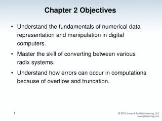
Step 22 • The default gateway IP addressis found in the Registry of the Windows device, and the ARP cache is checked to see if the hardware address has already been resolved from an IP address. • You can search the Registry by going into the Registry Editor (start/Run/regedit), then searching for “DefaultGateway” (F3 – enter search parameters). • See “Default” / “DHCP Default Gateway” next slide
Step 22 (continued) Above is a view of my home computer’s Registry settings: HKEY_LOCAL_MACHINE\SYSTEM\ControlSet001\Services\longkey\Parameters\Tcpip
Step 23 • Once the hardware address of the default gateway is found, the packet and destinationhardware addresses are handed down to the Data Link layer for framing.
Step 24 • The Data Link layer frames the packet of information and includes the following in the header: • The destination & source hardware addresses • The Ether-Type field [with 0x0800 (IP) in it] • The FCS field with the CRC result in tow
Step 25 • The frame is now handed down to the Physical layer to be sent out over the network medium one bit at a time.
Step 26 • The router’s Ethernet 1 interface receives the bits and builds a frame. • The CRC is run, and the FCS field is checked to make sure the answers match.
Step 27 • Once the CRC is found to be okay, the hardware destination address is checked. • Since the router’s interface is a match, the packet is pulledfrom the frame and the Ether-Type field is checked to see to what protocol at the Network layer the packet should be delivered.
Step 28 • The protocol is determined to be IP, so it gets the packet. • IP runs a CRC check on the IP header first and thenchecks the destination IP address. • IP does not run a completeCRC as the Data Link layer does—it onlychecks the header for errors.
Step 29 • In this case, the router does know how to get to network 172.16.10.0 — the exit interface is Ethernet 0 — so the packet is switched to interface Ethernet 0.
Step 30 • The router checks the ARP cache to determine whether the hardware address for 172.16.10.2 has already beenresolved.
Step 31 • Since the hardware address to 172.16.10.2 is already cached from the originating trip to Host_B, the hardware address and packet are handed to the Data Link layer.
Step 32 • The Data Link layer builds a frame with the destination hardware address and source hardware address and then puts IP in the Ether-Typefield. • A CRC is run on the frame and the result is placed in the FCS field.
Step 33 • The frame is then handed to the Physical layer to be sent out onto the local network one bit at a time.
Step 34 • The destination host receives the frame, runs a CRC, checks the destination hardware address, and looks in the Ether-Type field to find out to whom to hand the packet.