Download
1 / 25
250 likes | 464 Views
MECO Magnet Vendor Briefing at MT-18. October 23, 2003 Bradford A. Smith, MIT-PSFC MECO Magnet Subsystem Manager. Outline of Topics. Conceptual design overview A few words about procurement Draft SOW overview Magnet Work Breakdown Structure (WBS). Conceptual Design Status.

E N D
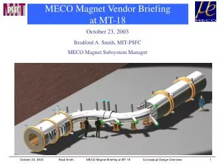
MECO Magnet Vendor Briefing at MT-18 October 23, 2003 Bradford A. Smith, MIT-PSFC MECO Magnet Subsystem Manager Brad Smith MECO Magnet Briefing at MT-18 Conceptual Design Overview
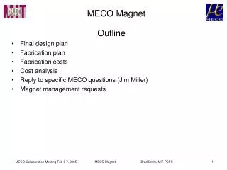
Outline of Topics • Conceptual design overview • A few words about procurement • Draft SOW overview • Magnet Work Breakdown Structure (WBS) Brad Smith MECO Magnet Briefing at MT-18 Conceptual Design Overview
Conceptual Design Status • MIT-PSFC completed in Feb02 a conceptual design* for the magnet system with a successful final review by a national review committee. • Conceptual design effort also included a detailed cost and schedule estimate for final design and fabrication • CDR Chapters 1. Introduction and summary 2. Interfaces 3. Field specs and field matching 4. Conductor design 5. Insulation design 6. Joint design 7. Current lead and bus bar design 8. Quench detection system 9. Quench protection system 10. Power supplies, dump resistors and switches 11. Structural design criteria 12. PS system stress analysis 13. TS system stress analysis 14. DS system stress analysis 15. Cryogenics system design 16. Magnet assembly 17. Magnet installation *Available: http://meco.ps.uci.edu/MIT_MECO_CDR.pdf Brad Smith MECO Magnet Briefing at MT-18 Conceptual Design Overview
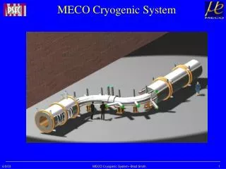
System Overview 29,000 kg + 28,000 kg 53,000 kg 53,000 kg Brad Smith MECO Magnet Briefing at MT-18 Conceptual Design Overview
Magnet Interfaces Current magnet interface information is available by WBS at http://meco.ps.uci.edu/ref_design/ref_design.html Brad Smith MECO Magnet Briefing at MT-18 Conceptual Design Overview
Field Requirements Magnetic field varies more or less monotonically from 5 T at the high field end of the PS to 1 T at the low field end of the DS. Field matching is required over a curvilinear cylindrical volume around the magnet axes as defined by a detailed specification. Field specification characteristics Brad Smith MECO Magnet Briefing at MT-18 Conceptual Design Overview
Field Solution Method • Postulate a set of n coils, coil builds and ampere-turns that might meet the field requirements. • Calculate fields at n points and influence coefficients for each coil at each point. • Calculate the field contributed by the iron. • Compare the field at n points against the field required by the specification. • Invert the influence coefficient matrix to obtain a corrected set of ampere-turns for each coil. • Check the field against the spec along three paths. • Iterate as required. • Final iteration and field calculation done with actual conductors, NI and builds Field specification paths Brad Smith MECO Magnet Briefing at MT-18 Conceptual Design Overview
Field Solution • A system of 94 solenoids, some with generally similar axial extent, but generally different radial builds meet the field requirement. • Coils are powered in 6 sets: • PS 3500 A • TS13u 1500 A • TS2 4000 A • TS3d5 1500 A • TS4 4000 A • DS 4000 A Conductor placement tolerance study indicated maximum current limits for TS and DS coils. TS Straight sections 1500 A TS Bends 4000 A DS 4000 A Brad Smith MECO Magnet Briefing at MT-18 Conceptual Design Overview
Conductors 1 • MECO has permission to draw from existing inventories of SSC inner and outer cable Conceptual design focused on and succeeded in achieving a design with acceptable margins using SSC cables Brad Smith MECO Magnet Briefing at MT-18 Conceptual Design Overview
Conductors 2 • Design guidelines • Fraction of critical: 0.65 (will be revised to 0.4), and • Temperature Margin: 1.5 K • SSC cables will be soldered into half-hard copper channels to meet protection guidelines (Max V = 2 kV, Max T = 150 K). • PS is subject to nuclear heat load Coil boundary (1st PS coil) He He Contours of constant temperature margin in high field PS coil Brad Smith MECO Magnet Briefing at MT-18 Conceptual Design Overview
Conductors 3 PS: 3500 A • Current limited by nuclear heating and temperature margin • 41 km of SSC Inner Cable (includes 25% overage) • fc = 0.31 • Bmax = 5.9 T TS: 1500 & 4000 A • Current limited by conductor placement tolerances • 30 km of SSC Outer Cable (includes 25% overage) • fc = 0.12, 0.28 respectively • Bmax = 3.5, 2.8 T, respectively DS: 4000 A • Current limited by conductor placement tolerances • 30 km of SSC Outer Cable (includes 25% overage) • fc = 0.26 • Bmax = 2.03 T Brad Smith MECO Magnet Briefing at MT-18 Conceptual Design Overview
Electrical Joints • Joints are lap solder joints Joints must meet the same margin requirements as the conductor: • Fraction of critical current: 0.65 ( 0.4 when updated) • Temperature Margin: 1.5 K • Conceptual design showed these margins can be achieved with the proper choice of solders and overlap lengths • Channel solder: 60Sn-40Pb • Hands solder: 44In-42Sn-14Cd (Indalloy #8) • Overlap length 2 cable twist pitches (~19 cm) Brad Smith MECO Magnet Briefing at MT-18 Conceptual Design Overview
Insulation • Turn + ground insulation is epoxy impregnated • Turn insulation • 1-mil, half-lapped Kapton + 3 mil, half-lapped fiberglass (S-glass in PS) • Voltage stress is about 10 V/mil on dump, max. for combined thickness • Ground insulation • Turn insulation plus 40 mil (1 mm) of fiberglass (S-glass in PS) • Voltage stress is about 40 V/mil on dump • PS Insulation must be designed to withstand nominal 30 Mrad • Radiation level is not significant for insulation compressive or shear strength. • Gas evolution deserves to be minimized. • Industrial study by Cryogenic Materials, Inc. recommended an epoxy system with the following components and cure: • DGEBF resin, 90 ppw, Vatico (Ciba Geigy) GY282 • PPGDGE toughener, 10 ppw, Dow Chemical DER 732 • DETD hardener, 26 ppw, Vantico (Ciba Geigy) HY5200 • Gel at 90 C for 15 hours • Cure at 130 C for 15 hours Brad Smith MECO Magnet Briefing at MT-18 Conceptual Design Overview
Quench Detection and Protection • Because all coil inductances are generally not alike, a digital quench detection system is proposed. • Each coil and coil-coil joint is voltage tapped. • In addition, all coil currents are monitored and dI/dt values are calculated. • System calibration is performed at installation during charge and discharge. • External dump minimizes helium loss and recovery times • MIT quench code (SOLQUENCH) has been run on the highest field coils in each of the PS, TS and DS; temperature distributions are output to ANSYS for structural analysis. Maximum hot spot temperature and maximum voltage requirements are met, while stresses and temperatures remain below allowables. Brad Smith MECO Magnet Briefing at MT-18 Conceptual Design Overview
Structural Design and Criteria Overview • MECO magnet system is divided into 4 magnet assemblies, each with its own cryostat: PS, TSu, TSd, and DS. • Division is based on shipping limitations and natural boundaries formed by each magnet’s function. • Loads between assemblies are reacted through their respective cold mass supports to the facility foundation. • Any or all coil groups may be energized • Warm bores may be at atmosphere or vacuum Design criteria • Combination of fusion and ASME criteria are used for guidance in coil structural design. • Fusion criteria allow primary membrane stress to be based on the lesser of 2/3 Yield (Sy) or ½ Ultimate (Su) when coils are supported by cases. • Otherwise ASME code criteria are used • Bases primary stress on 1/3 Su • Bending discontinuity and secondary stresses • Bolting and column buckling guidance is taken from AISC • Sy and Su are taken at the loaded temperature Brad Smith MECO Magnet Briefing at MT-18 Conceptual Design Overview
Coil Structures Production Solenoid (epoxy impregnated coils, bath cooled) Outer Al shells provide hoop load support Spherical-end rods take TS attractive loads He can designed for 5 atm (quench) Transport Solenoid(epoxy impregnated, conduction cooled) Coils are wound outside H-shaped SS mandrels Horizontal V formed by spherical-end-rod pair restricts horizontal motion at Be window Mid-span rod reacts centering load and is designed for tension only Vertical V spans proton beam port, provides lateral restraint and assists with gravity load Detector Solenoid (epoxy impregnated, conduction cooled) Uses spherical-end rods and H-shaped SS mandrels like TS Brad Smith MECO Magnet Briefing at MT-18 Conceptual Design Overview
Cryostats and Cryogenics All cryostats have stainless steel vacuum shells and LN2-cooled thermal radiation shields. • Production solenoid • Natural convection/force-cooled with 6700 liter LHe volume to safely remove 192 W of nuclear heat load at 4.5 K • 25 cm diameter quench vent stack keeps quench pressure below 5 atmospheres • Transport and detector solenoids • Lack of nuclear heat load enables conduction cooling • Inner and outer copper shells intercept radiation heat load and take it to He-traced copper heat sinks at the top of each coil Brad Smith MECO Magnet Briefing at MT-18 Conceptual Design Overview
Cryogenic Heat Loads Systemcomponent Refrigeration Liquid helium at 4.5 K consumption [Watt] [Liter/hour] TS 1 totals 20.18 17.6 Supports 12.8 Valves 1.37 Vacuum separators 0.86 Thermal radiation from 80 K 1.96 Conductor el ectrical joints (qty 35) 3.19 Current leads 17.6 TS 2 totals 20.13 17.6 Supports 12.8 Valves 1.37 Vacuum separators 0.86 Thermal radiation from 80 K 1.96 Conductor electrical joints (qty 33) 3.14 Current leads 17.6 DS totals 20.63 12.8 Su pports 6.04 Valves 1.37 Vacuum separators 0.86 Thermal radiation from 80 K 8.26 Conductor electrical joints (qty 24) 4.10 Current leads 12.8 Control dewar 1.3 PS totals 208.37 11.2 Supports 8.0 Valves 2.99 Vacuum separators 0.86 Therma l radiation from 80 K 3.28 High energy radiation 192 Conductor electrical joints (qty 10) 1.24 Current leads 11.2 PS dewar 1.3 GRAND TOTALS 269.31 61.8 Brad Smith MECO Magnet Briefing at MT-18 Conceptual Design Overview
Cryogenic Flow Diagram Current plan is to purchase a new refrigerator/liquefier to a spec developed by the magnet Vendor. System is designed to be flexible and accommodate all modes of operation Brad Smith MECO Magnet Briefing at MT-18 Conceptual Design Overview
Conclusions on Conceptual Design • Feasibility has been demonstrated. • Review (February 2002) was successful. • Led to further specific industrial studies that have been completed to reduce risk. • Insulation study • Refrigerator/liquefier study • Winding and impregnation approach • Magnet Tech Spec and SOW for procurement is being drafted. • Safety review studies have been initiated at BNL. • Results from Conceptual Design, Industrial and Safety Studies will be integrated into the Magnet Technical Specification and SOW for Final Design, Manufacturing, Installation and Commissioning. Brad Smith MECO Magnet Briefing at MT-18 Conceptual Design Overview
A Few Words about Procurement • Draft RFP • Based on draft technical and interface requirements. • Will be used to initiate response from industry • Contracting terms • Need for clarification • Final RFP • Based on final technical and interface requirements • Clarified technical and contractual requirements. Brad Smith MECO Magnet Briefing at MT-18 Conceptual Design Overview
Draft SOW - Overview Note: Arrangement below is based on the current draft document and is subject to change. • Items furnished by MECO project • SSC cable • General Responsibilities of the Vendor • Deliverables with the proposal • Final design • Fabrication • Installation • Acceptance test • Reporting Brad Smith MECO Magnet Briefing at MT-18 Conceptual Design Overview
General Responsibilities of the Vendor • The Vendor shall, unless otherwise noted, furnish all labor, materials, equipment and facilities to design, fabricate, assemble, install and test the MECO magnet system in accordance with the SOW/spec document. • Magnet system: conductor, coils, cold structure, cryostats, cold-to-warm and warm supports, PS and DS iron returns, bus and leads, control dewars, power supplies, quench detection and protection systems, cryogenic valves and piping, cryostat vacuum equipment, instrumentation and controls • Installation/acceptance test site: Brookhaven National Laboratory • The Vendor shall supply all documentation required in the specification. Brad Smith MECO Magnet Briefing at MT-18 Conceptual Design Overview
Preliminary Magnet WBS Brad Smith MECO Magnet Briefing at MT-18 Conceptual Design Overview
PS Magnet WBS (Lower Level Sample) Brad Smith MECO Magnet Briefing at MT-18 Conceptual Design Overview