Download
1 / 12
120 likes | 237 Views
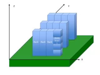
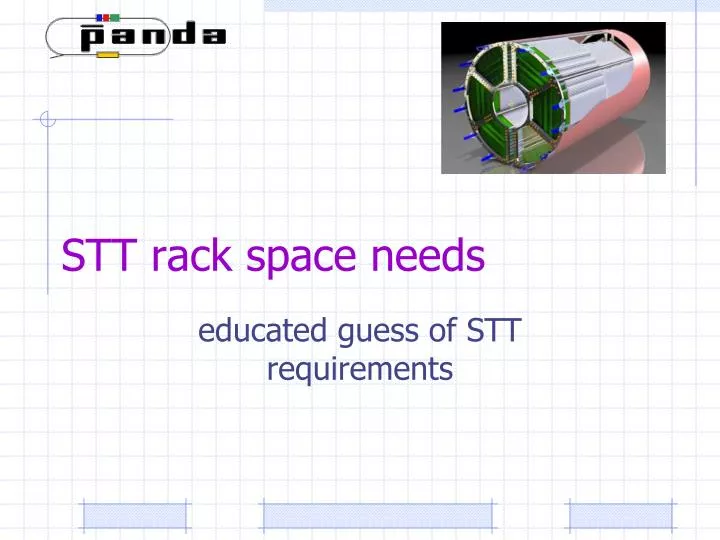
STT rack space needs. educated guess of STT requirements. TC is asking for. a) How many U rack space do you need at the detector? b) How many U rack space do you need in the supply level (E10) and the DAQ/readout level (E20) of the counting house?

E N D
STT rack space needs educated guess of STT requirements
TC is asking for a) How many U rack space do you need at the detector? b) How many U rack space do you need in the supply level (E10) and the DAQ/readout level (E20) of the counting house? c) Do you need any equipment close to the detector in non-standard (non-rack) housings? At which minimal distance to your detector and with which dimensions? The dead line to provide info is next TB in Bochum
STT numbers • 4636 Straw tubes arranged in planar layers (24-27) • Time readout (isochrone radius) drift time ~ 200 ns (B=2T) req. electronic resolution < 1 ns sensitivity (threshold) ~ 2 fC • Amplitude readout (energy loss) • Straw tube capacitance: ~ 10-15 pF (9 pF/m) impedance: 373 Ώ inductance:1.24 μH/m • Gas volume: ~ 1040 l • mixture 90Ar + 10CO2 xy-view
Readout scheme • FEE anlog: • Preamp+ Shaper+ BLR + Discriminator • Analog output needed for dE/dx measurement? • Digital Boards: • Multihit TDC: Time measurement + TimeOverThreshold (TOT) for chargemeasurement OR/AND analog signalprocessing via FADC • Zerosuppression & Hit detection. Slow /Run/Data flowcontrol • Data Concentration: • gathering and sorting of hitsmarked by timestamps in epoques (i.e 500 s bunch) • nGbit/s Optical serial link Located on the STT FE DB Located on racks outside
FEE Boards Tentative layout of FEE boards. Total # 592 includes some spare channel. Cooling is not yet excluded.
Digital+Concentration Boards These functions are implemented in TRBv3. • 5x Lattice ECP3 150 FPGAs • 4 edge devices up to 60 TDC ch • 1 central for control • Flash ROMs for each • 4x 208pin QMS connectors • Small Addons • 2x80pin connectors • Large Addon (i.e. ADC) 24 TRBs will instrument all STT Which kind of Crates? 9U, 6U How many?
HV system How much space? • Based on Wiener Mpod (8U) - universal multi-channel LV/ HV power supply system • Controllerwith Ethernet, CANbus, USB interface, and • interlock; • Web-ready and TCP/IP communication via SNMP, OPC server; • LabView software support; • LV and HV modules freely combinable; • High Voltage modules (ISEG) with 8, 16, 32 channels of from 500V to 10kV, floating or common ground; • Low Voltage floating modules with 8 channels of 10A / 50W max. with 8V, 16V, 30V, 60V ranges • - PXI platform from National Instruments as I/O • Controller • Embedded controllers with Intel CPUs, hard drive, • memory, Ethernet, video, serial, USB, GPIB; • - OS support: Windows, LabView Real-time, Linux; • - more than 1500 PXI products (Multifun. DAQ, FPGA)
Slow Controls ARM-processors (CPU based on simplified instruction sets) will control different field points (gas/pressure controllers, temp. sensors, etc. )
DCS and HV systems Regarding rack space for the DCS and HV System: - ethernet switch: 1 U - epics gateway server : 2U - NI PXI Crate: 4U - MPOD Bin: 9U ________________ total: 16U
Cables and supply lines • - The STT readout ASIC will provide LVDS differential outputs. • It will have 8 channels/chip and 2 control lines. Therefore for each chip we will need a 10 pairs flat cable.Total # of flat cables is 296x2. • These cables should be connected to patch-panels locate outside the magnet • ~1240mmx1200mmx150mm • Forthe gas weforesee 24 gas supplylines, 224 gas pipes (in-/outlet). • Weneed also 40 HV cables. • Howmanycontrollinesfortemperatureandpressure? • Thresholdsettingandtestpulsesfor FEE arealreadyincluded?
Timeline and Milestones • Prototype/Pre-series testing complete, production readiness • Mass production • Ready for installation • Ready for beam (commissioning) 2014 2015-2016 2017 2018