Download
1 / 43
430 likes | 626 Views
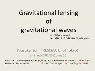
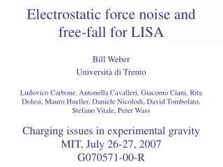
Free-fall and the observation of low frequency gravitational waves with LISA Bill Weber Università di Trento Caltech March 24, 2006. LISA. Laser Interferometer Space Antenna. LISA: an orbiting observatory for low frequency gravitational waves.

E N D
Free-fall and the observation of low frequency gravitational waves with LISA Bill Weber Università di Trento Caltech March 24, 2006
LISA Laser Interferometer Space Antenna
LISA: an orbiting observatory for low frequency gravitational waves Sensitivity curve for 1 year integration and S/N=5
Purity of free-fall critical to LISA science Example: massive black hole (MBH) mergers Integrated SNR at 1 week intervals for year before merger Assuming LISA goal: Sa1/2 < 3 fm/s2/Hz1/2 at 0.1 mHz • Factor 10 in acceleration noise decreased observation time (year weeks) • LISA sweeps out only 10 degrees rather than a full circle • Lose information on source location and thus source luminosity distance How “guaranteed” is LISA’s low frequency sensitivity and projected scientific return?
What are the sources of force noise that can compromise purity of free-fall for LISA? • What is the proposed “drag-free control” system that aims to minimize force noise? • What do we know and what can we learn quantitatively about these sources of force noise? • LISA Pathfinder in-flight test • torsion pendulum studies on the ground
Relative position measurement xm Spacecraft shield (mass M) “internal” stray forces fstr Springlike coupling to spacecraft motion (“stiffness”) mwp2 external forces on satellite Fstr Residual acceleration noise: Stray forces and drag-free control • Solar radiation pressure would give 10 nm / s2 acceleration to 1 kg test mass mNewton Thrusters “Drag Free” loop gainMwDF2 m
Springlike coupling to spacecraft: sensor readout stiffness (wp2xn~ d) gravity gradients External forces with finite control loop bandwidth Residual acceleration noise: gas damping magnetic noise readout back action (~ d-2) DC electric fields + charge shot noise (~ d-1) DC electric fields + dielectric noise (~ d-2) thermal gradients radiation pressure, radiometric effects Sensor noise Low frequency stability! Key LISA test mass acceleration noise sources dx Gap
VACT1 Cp Cp VACT2 VAC 100 kHz Cs1 L VM Cs2 L Gravitational Reference Sensor Design • ~ 1 nm/Hz1/2 sensor noise floor • low force gradient (k ~ 100 nN/m) • low force noise (Sf1/2~ fN/Hz1/2) f xm k • 40-50 mm cubic Au / Pt test mass (1-2 kg) • 6 DOF “gap sensing” capacitive sensor • Contact free sensing bias injection • Resonant inductive bridge readout (100 kHz) • Audio frequency electrostatic force actuation • avoid DC voltages • Large gaps (2 – 4 mm) limit electrostatic disturbances • High thermal conductivity metal / ceramic construction • limit thermal gradients
+ dVACT vth-s + dCfb Cp Csens1 dV1 vth vamp + dL vth-fb + dVAC Q iamp VM dV2 Cp Csens2 - dL vth-s • Bridge thermal noise at 100 kHz + dVACT • Amplifier and feedback noise • Actuation noise at DC, 100 kHz, and fACT Disturbances analyzed for readout noise, but also as force noise sources • Voltage and component stability • DC biases and test mass charging • Low frequency thermal noise Capacitive sensing readout / actuation scheme: Modeling of position and force noise VACT1 Cfb VAC 100 kHz L n2L L VACT2
Acceleration noise projections for LISA [Note: “worst case,” assume performance at 0.1 mHz across whole band] How do we verify these predictions for acceleration noise?
~ 5.106 km ~ 30 cm TM1 TM2 ESA / NASA LISA Pathfinder Mission Launch 2008 Testing TM free-fall purity to within an order of magnitude of the LISA goals LISA: ares < 3 10-15 m/s2/Hz1/2 f > 0.1 mHz LTP: ares < 30 10-15 m/s2/Hz1/2 f > 1 mHz
LTP Configuration, Dynamics, and Measured Quantities Xbase + d xbase ~ 30 cm electrostatically suspended drag-free x TM1 TM2 Dx1 Dx2 Dx1 Dx12≡x2 - x1 Noise: xn1, xn2 xn,opt Capacitive position sensors Relative displacements Dx1, Dx2 Optical interferometer Differential displacement Dx12 Relative displacement Dx1 • Control scheme: • Satellite follows the “drag-free” TM1 with drag-free gain wDF2 • TM2 electrostatically forced to follow TM1 (null Dx12) with gain wES2 • Relative displacement Dx12 measured with interferometer to probe drag-free performance • Note: wES2 , wp2 << w2 << wDF2 2 Masses, 1 measurement axis (x)
TM1 TM2 Dx12 • differential stiffness, nominally zero • tune to zero electrostatically • isolate force noise • for xn,opt~ .1 nm/Hz1/2, measure random differential force noise S1/2Dfto~ 5 fN/Hz1/2 LISA LTP Measurement of stray force noise fstr
Dx1 • optical interferometry measurement of TM1 with respect to satellite gives redundant, higher precision measurement of Dx1 measure sensor noise S1/2x1n LISA LTP Measurement of External Force and Sensor Noise • Closed-loop: satellite control nulls the sensor 1 output to an accuracy limited by the finite gain control loop response to external forces TM1 TM2 Dx1 Fstr
TM1 TM2 Dx12 LISA Drag-free control setpoint modulation: stiffness measurement • control satellite to TM1 to a modulated setpoint x0 sinwt • control TM2 to follow TM1 (mode 3) • “shake” satellite, observe differential motion • acceleration noise limited differential stiffness resolution: • Roughly 2% of LISA stiffness goal of 4 10-7 /s2 • Other schemes allow 10-20% absolute stiffness measurement via sensor signal
TM1 TM2 Measurement of coupling with magnetometer and field/gradient coils • Thermal gradient effects • radiation pressure difference • radiometric effects • temperature dependent outgassing TM1 TM2 Measurement of coupling with thermometers and heaters Coherent force measurements: Magnetic field effects • Measurement of disturbance time series allows correlation analysis of noise sources, measurement of actual coupling parameter allows possible correction • LTP is a true experiment, “debuggable”
LTP “instrument noise limit” • resolution with which we can measure LISA force noise • 5 fm/s2/Hz1/2 (within 2 of LISA goal at 1 mHz) • limited by interferometer and actuation noise LISA goal
Torsion Fiber Torsion pendulum measurements of small forces originating in gravitational reference sensor Light-weight test mass suspended as inertial member of a low frequency torsion pendulum, surrounded by sensor housing Measure stray forces as deflections of pendulum angular rotation to within 100x LISAgoal, 10x LTP goal Mirror for Optical Readout Test Mass inside Sensor Housing Precision coherent measurement of known disturbances Sensing electrodes 1 2 gap d Pendulum suspension and axis of rotation Sensing electrodes separation
Results obtained with 2 different sensors Trento prototype LTP EM sensor Design differences Gaps: 2 mm 4 mm further reduction of short range electrostatic effects Injection electrodes: z-axis y and z axes favors x axis Electrode material: Au coated Mo Au coated ceramic (shapal) better machining tolerances risk of exposed dielectric Construction techniques: HV glue / screws, pin contacts LTP Flight Model Sensor – Au coated sapphire electrodes
Force noise measurements: more stringent upper limits Pendulum angular deflection noise measured over 3 days
Force noise upper limits (old sensor) LTP Goal (most pessimistic torque – force conversion, 10.25 mm)
Force noise upper limits (new sensor) LTP Goal Excess noise observed below 1 mHz rises more steeply than thermal noise Observed with both sensors likely pendulum (not sensor) related Currently under investigation!
SENSOR OFF SENSOR ON Noise source characterization Stiffness: coupling to spacecraft motion Move sensor (or spacecraft), measure force (or torque) • Coherent torque excited by square wave oscillation of sensor rotation angle • Search for all sources of stiffness, with and without sensing bias Results: G = GSENS + G0 GSENS = - 89.2 ± .5 pN m / rad consistent with expected sensor bias stiffnes G0 = - 12.0 ± .3 pN m / rad extra stiffness ... could be explained by 115 mV RMS patch voltages SENSOR ON SENSOR OFF
Stiffness with 4-mm gap sensor Sensor ON electrostatic stiffness roughly as modelled Sensor OFF stiffness essentially zero “extra” stiffness not observed With 4 mm gap sensor, unmodelled force gradients are not likely to be an issue for LISA
DT Noise source characterization Thermal gradient measurement • (Noisy) temperature gradient converts to (noisy) force: • radiation pressure • radiometric effect • temperature dependent outgassing (???) In the lab (and on LTP) apply DT measure force (torque)
Thermal gradient measurement: pressure dependence • radiometric effect as expected • N(p=0) increases with temperature as expected • measured torque is consistent with radiometric+radiation pressure effects • (factor » 2 uncertainty in effective DT) Measured value ≈ 1 10-7 mBar Theoretical ≈ 1.5 10-7 mBar Largely independent of DT, geometry • we actually see too small a torque coefficient • radiation pressure effect probably overestimated (not infinite plates) • any temperature dependent outgassing effect is too small to hurt LISA
Noise source: DC biases dV2 dV1 VM Dx Electrostatic stiffness Random charge noise mixing with DC bias (Dx) Noisy average “DC” bias (SDx) mixing with mean charge Noisy “DC” biases interacting with themselves
VD 1A 1B dV1A dV1B 2A 2B dV2A dV2B Individual noise source characterization DC Bias: measurement and compensation Average DC bias difference couples to charge shot noise • Apply “charge”, measure force (extract DV) • Compensate DV • DC biases of order 10’s of mV would be a relevant noise source • Sub-mV compensation demonstrated with torsion pendulum, possible in flight • Random charging should not be problematic under normal conditions
vn dV Noise source: in-band voltage noise mixing with DC bias • Voltage noise: vn • Actuation amplifier noise (electronics) • Thermal voltage fluctuations (d) • Drifting (not Brownian) DC bias SdV1/2 • DC voltage difference: dV • Residual unbalanced patch effects • Test mass charge LISA requires vn≈ 20 mV/Hz1/2
Measurement of dielectric losses: new direct measurement technique Circuit + surface losses Force (torque) quadratic in voltage 1W 1E perfect square wave voltage produces only DC force (torque) 2W 2E Force: Electrode voltage: No losses Ohmic delay d constant
DC Bias effect Force transient due to delay DC Bias effect Measurement of dielectric losses: new direct measurement technique Application of perfect square wave yields constant force Any lossy element creates delays and thus force transients Direct application (f = .4 mHz) Application through an ohmic delay (t≈ 7 ms, d ≈ 2 10-5) 390 kW 19 nF
Dielectric Loss Angle Measurement Results • 2w cosine torque frequency dependence ohmic delay time t≈ 0.3 ms (agrees with calculated value) • 2w sine + cosine intercept values d≈ 10-6(likely not a problem for LISA!!)
DC Bias measurements: stability 4 day measurement of residual DC balance stability after compensation • Observe long term drifts in the DC bias imbalance of mV over several days
DC Bias measurements: stability LISA goal • Limited by pendulum force noise measurement resolution above 50 mHz • excess noise (drifting) below 50 mHz • current measurement resolution not sufficient to guarantee LISA performance!
Continuous charging with UV light 2 UV fibers illuminate TM and/or electrodes for bipolar photoelectric discharging TM ONLY ELECTRODE LAMP = 5 TM LAMP = 100 Cancelling charge rates of +35000 /s and -35000 / s EL ONLY
Torsion fiber Twist angle Magnetic testing of full Au – Pt test mass • Measuring LISA TM magnetic properties (residual moment and susceptibility) with a torsion pendulum Holder and mirror for optical readout Applied B field • Measure moment detection with pendulum deflection in homogeneous field • Measurement of susceptility (c) requires non-zero second derivative of B (2f signal, analysis in progress)
Development of Four-mass torsion pendulum • in LTP / LISA, force matters (not torque!) • Direct sensitivity to net forces (Fx rather than just Nf) not achievable with 1-mass pendulum design • thermal outgassing, DC electrostatic problems could arise at central edges of the electrodes • translational stiffness qualitatively different from rotation stiffness with current electrode design
Four-mass pendulum: facility construction Go big(*) or stay home! Torque signal (*) How big? Gravitational gradient noise • First inertial member has arm length R = 10 cm • Gravitational gradient measurements underway
Four-mass pendulum: initial testing with prototype inertial member • “blank” measurement to measure pendulum noise in absence of sensor • thermal noise, twist/tilt, temperature sensitivity, gravity gradient noise
Preliminary data 4 mass pendulum Pendulum ready to make relevant direct force measurements for LISA
LISA low frequency sensitivity goal requires test masses to be in perfect free-fall to within 3 fm/s2/Hz1/2
Trento physicists* contemplate free fall and free food while celebrating the PhD of Doctor Ludovico Carbone [* minus Antonella Cavalleri, plus Tim Sumner] Michele Armano Ludovico Carbone Antonella Cavalleri Giacomo Ciani Rita Dolesi Mauro Hueller David Tombolato Stefano Vitale Bill Weber Trento LTP / LISA Group