Download
1 / 31
310 likes | 327 Views
This review discusses the design of the Calorimeter Digitizer system, including the overview, block diagram, major components, power, and status.

E N D
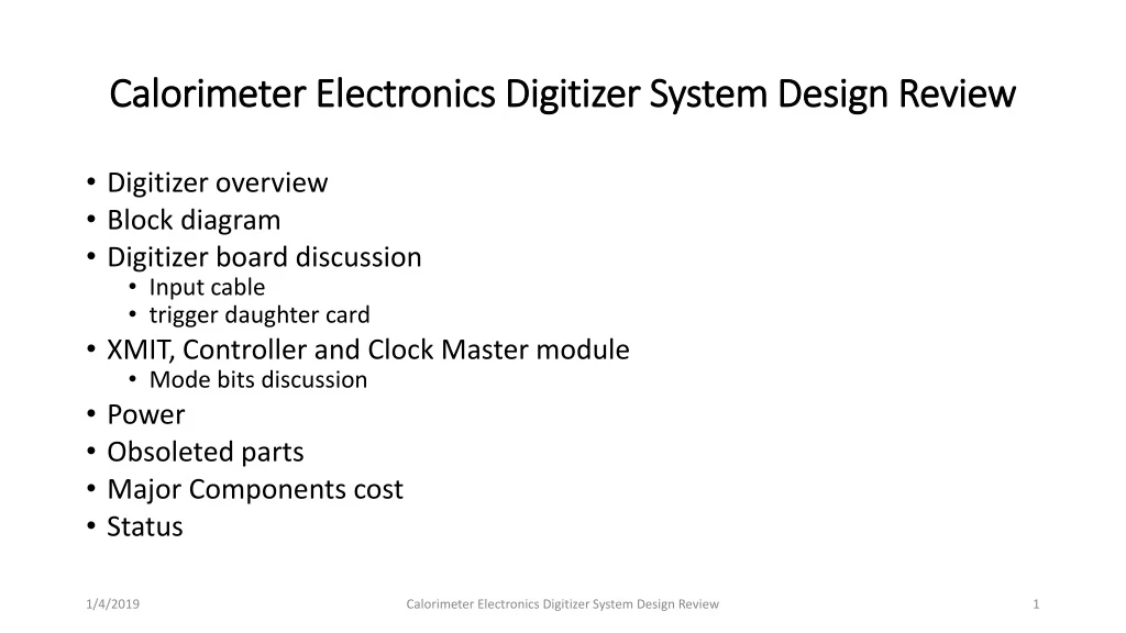
Calorimeter Electronics Digitizer System Design Review • Digitizer overview • Block diagram • Digitizer board discussion • Input cable • trigger daughter card • XMIT, Controller and Clock Master module • Mode bits discussion • Power • Obsoleted parts • Major Components cost • Status Calorimeter Electronics Digitizer System Design Review
Calorimeter Digitizer system overview • Off detector ADC system for both EM and Hadronic calorimeter. • Received the amplified signal from on-detector amplify through cables • Digitize the signal at 6x beam crossing rate, ~ 60 MHz, with 14 bits ADC • Offset the baseline to use most of the ADC range. • Provide at least 40 beam crossing of data buffers to cover L1 trigger latency • Provide Level 1 trigger primitives. • Minimum 4 Level 1 events buffer. • Maximum 31 ADC samples per channel per events, 16 samples planned. • 15 KHz Level 1 trigger rate (16 Samples/channel/Event). • Send Level 1 trigger events to the DAQ system. • 24576 EMCAL channel, 1536 HCAL Channel. Calorimeter Electronics Digitizer System Design Review
The Subsystem Technical Overview Crate based system. Signals are cable from the on-detector electronics. Digitized with 14 bit ADC. Receive timing information the SPHENIX Granule Timing Module (GTM) Generate L1 trigger primitives Receive L1 trigger and send out L1 triggered event data to Data Collection Module II (DCMII). Provide buffer for both the 40 beam crossing L1 delay buffer and 4 L1 triggered events crate Clock are fanout point to point through the backplane Trigger out Trigger out Slow control/readback bus, L0, L1 trigger Token passing dataway Token passing dataway XMIT Controller ADC ADC 3 ADC XMIT (rack based) detector clockmaster 3Gbit/sec optical link 1.6Gbit/sec optical link Slow control/readback Beam clock, L0, L1 trigger DCM II JSEB II GTM SPHENIX DAQ System PC Calorimeter Electronics Digitizer System Design Review
sPHENIX ADC Module Block Diagram RHIC beam clock 9.6MHz +4V, -3.5V, +2.5V Power 7X ADC clock Analog Device AD9257 8 channel 14bits 65 MHz ADC +- 3.5V, -2.5V Differential receiver power +1.8V analog ADC power +1.8V digital ADC power F R A M E ALTERA Arria V GX BB1D4F35 1152 pins FPGA 6x beam clock Beam phase, init, L1 Serialized ADC DATA Differential receiver De-serializer D P U two transceivers 2 mm Hard Metric Token Passing Data 5 L1 Accepted Event buffer L1 Delay Buffer Serialized Token Passing Clock Fanout 64 channel ADC board 6 X beam clock Serial command two transceivers 2 mm Hard Metric L1 trigger primitives transceiver out command/ offline data read De-serializer F R A M E Differential receiver Serialized ADC DATA Bused command Serial data 3.3V LDO 3.3V LDO Analog Device AD9257 8 channel 14 bits 65 MHz ADC DC/DC switch regulator 4V +12V Power DC/DC switch regulator 2.5V FPGA I/O 7X ADC clock 1.5V LDO 1.1V core Calorimeter Electronics Digitizer System Design Review
The ADC system has 14 bits output (0- 16383 ADC counts) The ADC input is differential, need to supply both + and – inputs ( peak-peak range is 2V) (122 mV per ADC counts) +1V on the positive side and –1V on the negative side 8192 ADC count happened when V+, V- difference is zero Our signal only swing one side To get full range we need to offset the signals. (the point to introduce the noise) 0.1% close match resistors Calorimeter Electronics Digitizer System Design Review
Signal input cable • Put as much signals into the small space as possible • Match the 8 channel ADC foot print. • That also match the FPGA foot print • High packing density also mean lower cost forthe reset of the system components • Crate, controller, XMIT etc. • Want to keep signal cross talk as low as possible. • Individually shield cable are the best. • 2 MM hard metric has low cable volume, shield cable and high packing density • 2mm for 2 sets differential signals. Calorimeter Electronics Digitizer System Design Review
The Choice of ADC Analog device AD9249 16 channel 14 bits ADC. Maximum sampling rate 65 MHz SNR 75db 1.8v technology. 58mw per channel at 65 MHz -> 1 W per chip. 144 pins package. 1cm X 1cm BGA pipeline latency 16 clocks. Analog Device AD9257 8 channel 14 bits ADC Maximum sampling rate 65 MHz SNR 75.5 db 1.8v technology. 55mw per channel at 65 MHz 65 pins LFCSP package. 0.9mm by 0.9mm. pipeline latency 16 clocks. Texas instrument ADS5294 8 channel 14 bits ADC. Maximum sampling rate 80 MHz SNR 75.5db 1.8v technology. Per channel 58mw at 50 MHz, 77mw at 80 MHz. 1-wire only interface only for below 50 MHz sampling 80 pins QFP package. 12mm by 12mm included digital processing block ( only after digitization) pipeline latency 11 clocks for 1 wire interface. Linear Technology LTM9008-14 8 channel 14 bits ADC. Maximum sampling rate 65MHz SNR 73 db 1.8v technology. Per channel 88mw at 65 MHz. 140 pins BGA. 11.25mm X 9mm pipeline latency 6 clocks. • The limit of ADC LVDS serializer • seems to be less than 1Gbits/sec • 65 MHZ ADC • The FPGA does not have 128 LVDS • De-serializer 1 LVDS output • per ADC channel • JSED204B’s ADC need the transceiver to receive data • Limits number of ADC can be connected to the reasonable price FPGA Calorimeter Electronics Digitizer System Design Review
Sphenix 64 channel ADC Data Flow Diagram BC & L1 event numbers Header 512X16 Header 8 x 32 Beam clock number 6x RHIC clock 6x RHIC clock L1 trigger 8b/10b encoding Serialized data from down Stream board 14 bits ADC serialized data 840 Mbits/sec LVDS L1 Delay memory 512X128 8 events buffer 256 X 1024 FIFO 2048 * 34 bits (first, data, Last) Alignment 16bits FIFO Gbits receiver Input control De-serialize /alignment 1-8 16bits FIFO Gbits receiver Fake data 512X16 1-64 channels wadd Token in radd = wadd - delay 8b/10b encoding Serialized data Gbits transmitter Link control L1 trigger Primitives generators Token out 120 MHz Reference clock 80 MHz Reference clock Write address 3 bits events, 5 bits samples Gbits transmitter write = valid & token Read = !empty read address 3 bits events, 5 bits samples LVDS repeater Slow control readback backplane Optical transceiver Lemo out Daughter card Calorimeter Electronics Digitizer System Design Review
Cal trigger primitive Generator (preliminary) 6X BC clock 120 MHz clock 12X BC Clock delay +1 +2 + 1 BC + 2 12X +1 4 bits trigger phase only use upper 8 bits Dual port memory Baseline subtraction Lookup memory (1024X10) Choose one of the of of the 12X BC clock phas for trigger primitive 10 bits 2X2 SUM (12 bits output) MUX 128 bits To 8 16 bits 10X16 bits FIFO Transceiver IP Read Address (upper 10 bits) Load lookup Memory from Slow control Read address = write address -delay Sub = ADC – ADCpre If (adcpre> adc) sub=0 64 channels 16 2X2 8 bits sum Delay a parameter Probably has 2 clocks offset Monitor Delay dual port memory 5 events buffer To controller readout Delay and # of Sample adjustable L1 trigger Calorimeter Electronics Digitizer System Design Review
ADC board FPGA Image Storage • ADC board use EPCQ256, 256 Mbits, as ARRIA V FPGA boot eprom. • The ARRIA V B1 need 137 Mbits of space if data is not compressed. • Compressed version use lot less than full capacity. • If one used compressed images, The EPROM space can be divided into 2 spaces, the “default” image and “running” image. • The default image will be the one used when system power up. • The running image will be boot up with serial command from controller with timer enable. • If timer expired, the board will be fall back to the default image. • Timer need to disable after reboot. • The default image allow us to reprogram the running image. • The programming time can be long because long EPROM write cycle Calorimeter Electronics Digitizer System Design Review
adc ADC Board Performance (baseline, no signal) Channel 1 without offset Baseline (average ADC) Ch 0 nhits Channel number adc Ch 1 nhits sigma Baseline (sigma) adc Ch 2 nhits Channel number adc Ch 3 nhits Rohde & Schwarz HMP4040 Power supply adc Calorimeter Electronics Digitizer System Design Review
Pulse shape channel 40 rms Digitalized pulse from Charge injector triggered by the FEM and trigger daughter card ADC Sample number ADC Charge injector FEM Trigger daughter card rms ADC ADC Calorimeter Electronics Digitizer System Design Review
Trigger daughter plug in from the back with 2 outputs, 1 optical transceiver, 1 lemo output. backplane Optical transmitter output ARRIA 5 FPGA LVDS buffer Lemo out Trigger daughter card 3.3v Calorimeter Electronics Digitizer System Design Review
Prototype Boards Custom ADC system backplane ADC board ADC XMIT board ADC crate controller Calorimeter Electronics Digitizer System Design Review
SPHENIX ADC backplane Block Diagram 6X Clock fancout 10 bits 2 frame+ 8 bits 10 bits 2 frame+ 8 bits Slow read- back Slow read- back Slow read- back Slow read- back 2mm HM 3V power 3V power Rear mount Trigger board Rear mount Trigger board Rear mount Trigger board 2mm ZD Trigger Primitives + single trigger bits out Serialized Trigger data Trigger/evwnt data/ l0 timing Serialized Triggered data 2mm ZD Token in Token out L0 timing Running 6X beam rate 6 bits per beam crossing 2 links per side (even, odd modules) 2mm HM Slow control Down-load Slow control Down-load Slow control Down-load 10 bits 2 frame+ 8 bits Slow control clock (1.5X beam clock) controller ADC XMIT Calorimeter Electronics Digitizer System Design Review
Agilent scope 12 GHz 40G samples/sec Agilent 3.5GHz 1131A differential probe Persistence display Trigger board waveform Measure at Trigger daughter card transceiver input Signal speed 2.4 Gbps 200ps per division 500ps per division Calorimeter Electronics Digitizer System Design Review
ADC board token passing data waveform ADC L1 event data has 2 token passing links. Each link has pair transceiver channel. The transceiver has 80 MHz reference clocks. The transceiver can be run at 640 Mbps , 800 Mbps or 1.2800 Mbps. The XMIT data links speed to DCM II is 1.6 Gbps. 1.6 Gbps per link 640 Mbps per links 1ns/division 2ns/division Calorimeter Electronics Digitizer System Design Review Token passing receiver side on the backplane
XMIT MODULE • Receive ADC module L1 triggered event through 2 token passing link. • The link composes by 2 transceiver links. Each links speed can be run 640 Mbps, 800 Mbps and 1.28 Gbps. • The L1 triggered events data will be send to DCM II. The DCM link speed is 1.6 Gbps. • Token get generate when receive L1 trigger and previous events transferred is finished. Otherwise token will be generated when currenttransmission is done. • A up and down counter provide multiple L1 triggers. Increment by 1 when receive L1 trigger. Down count by 1 when data are send. • 1 events has 2304 16 bits data words = 3 ADC module * 64 channel *12 samples per channel. • 2 640 Mbps links will transfer 16 bits data word every 16ns. 2304 words will takes 37us. DATA FLOW 6x CLOCK RCV ALTERA CYCLONE 4 GX RECEIVERS F I F O OPTICAL TRANSCEIVER TLK 2501 (SERIALIZER) TOKEN CONTROL REFERENCE CLOCK Mode Bits Slow download/control Calorimeter Electronics Digitizer System Design Review
sPHENIX Digitizer Crate Controller • Receive 6x beam clock and Mode bits information (L0, L1 timing) through single USB 3 connection. • Provide offline clock and offline mode bits generator • Provide slow control & download path and offline readback function through JSEB II interface via optical cable. • JSEB II PCI interface. • Di-directional link. • Control and download path to the MBD discriminator and pulse shaper electronics. • Second generation board. • Previous board does not have clock master input. • Optical link to the PCI express will only run at 2.5Gbits/sec • Default to offline mode when power up and JSEB II optical link is down, • Will provide status readback on the clock input status Beam Clock diff. receiver PLL mux Clk fanout clk USB 3 connector Offline clock 60 MHz Slow Control readback clk Mode bits diff. receiver on line/ off line Altera Cyclone 4 GX Mode bits out From JSEB 2 Optical transceiver Ref clk 125 MHz Slow Control send pulse Ext trig in Slow Control to MBD Twist Flat cable Calorimeter Electronics Digitizer System Design Review
sPHENIX Digitizer Clock Master Interface to the sPHENIX Timing system. 6x recovered beam clock, receiving mode bit serialized to 6x beam clock (BC phase included) provide beam clock for the MBD FEM. output mode bits, 6x clock via USB 3 cable. TLK1501, configured as receiver only, has a narrow frequency to lock incoming data. A plug in module with reference frequency is used for difference collision spec. TLK1501 uses 8b/10 encoding method, need either <K28.5, D5.6> or <K28.5, D16.2> to lock or relock to the link. No external control. It will serve as dumb interface. Diff. PECL Driver MBD Beam clock Pair-Of LEMO 1:4 fanout Altera Cyclone 3 TLK 1501 Optical transceiver 6X Beam clock 1:4 fanout GTM 1:4 fanout Ref clk 1:4 fanout LVDS USB 3 Plug in module Mode Bits 1:4 fanout 1:4 fanout LVDS USB 3 Calorimeter Electronics Digitizer System Design Review
Mode Bit Discussion • The GTM Link will serve for clock and L0, L1 timing information • The recovered clock will be 6x beam clock. • 16 bits data field will have mode bits (init, reset, test etc) BC phase, L1 trigger etc. • The 8b/10 encoding need to have a) frequency lock, date phase bit lock and serial to parallel conversion. • Need to deal with lock and re-locked the link • For TLK chip, 3 fill frame is necessary for that. • Most us need only one data word out of 6 data from 6x beam crossing. • Suggest we send 3 fill frames per beam crossing. • No special stated needed to lock on both side to start the link. • Automatic recovery if the link ever lose lock. • Does not know about the recovered clock during loss lock and relock period. Calorimeter Electronics Digitizer System Design Review
Digitizer Mechanical • All module is 6U height and 190 mm long. • 190mm is not standard depth. But the ADC module layout requires longer depth. • The mechanical spec follow IEEE 1101.10. • The backplane are custom. But mounting holes, width and length follow 1101 standard. • Because we use 2mm HM cable for signal cable inputs. Front panels have to shift by 0.153 inch from the normalmounting position. Injector/ejector position unchanged. • The crate is custom design by ELMA. • Move backplane mounting position. Calorimeter Electronics Digitizer System Design Review
sPHENIX Calorimeter Digitizer Backplane (power) +2.5V & +12 V power Use Molex Z power 76001-0010 50A capacities. -3.5V and +4V power Use Tyco 9-55556-0 25A each ERNI 2mm HM power connector 114404 for digital power (+12V, Ground, +12V) 254927 for analog Power (G, +2.5V, G, +4V, G, -3.5V) 10.8A current capacity. Fit 1101.10 6U backplane mechanical size +2.5V, +2.5V return +2.5V, +2.5V return +2.5V, +2.5V return -3.5V, return, +4V -3.5V, return, +4V Analog Power +12V, +12V return +12V, +12V return Digital Power Calorimeter Electronics Digitizer System Design Review
Power • We have +12V for digital power, -3.5V, +2.5V, +4V for analog power supplies. • Only ADC board use analog power • All modules has fuses and Zener diodes. • Fuses are plug in through Amp 2-5331272-7 socket. Calorimeter Electronics Digitizer System Design Review
Obsolete Parts • Altera has discontinuation of their EPCQ and EPCS components: • We have brought Winbond W25Q256 NOR flash memory to replace EPCS16. • Package and pin compatible. • W25Q256 is also obsoleted. We have plenty of the Winbond chip. • EPCS are used in the XMIT module. • The new Micro serial NOR memory, MT25QL256 is compliable wit EPCQ256. • Altera has app note about the replacement. • The new NOR memory has considerable faster than EPCQ256 with much lower cost. Calorimeter Electronics Digitizer System Design Review
Major cost of the system • The cost drivers are on the ADC board, 276 production boards. • The 8 channel Analog Device ADC AD9257 ($84 per chip) • 64 channel board 8 ADCs per board • The Altera Arria 5 FPGA ($322.10 per chip) • receive the ADC data and data manipulation, L1 delay, 5 events buffer and generating trigger primitives. • The differential receiver, AD8132 ($2.10 per chip) • Receiver the differential signals from the cable. One per channel. • The PCB board ($210 per board) • The PCB assembly ($285 per board) Calorimeter Electronics Digitizer System Design Review
Status • The digitizer board, XMIT board, crate backplanes, crate controller (v1) has been build and tested in both BNL and Nevis. • It is also been used in the Fermi Lab test beam effort • The Crate Controller (v2) and Clock Master board has been fabricated. • Testing in progress. • Work reasonable well Calorimeter Electronics Digitizer System Design Review
Backup Slides Calorimeter Electronics Digitizer System Design Review
Digitizer board power • 2.5 V 2A to start. After ADC reset, PLL The power is 2.3A. • -4V 0.8A • -3.6V 0.73A • Trigger daughter card • AFBR_59RLZ 760mw max. 3.3V power • NL37WZ16 100ma max 3.3V • Power through ADC board with 3 ERNI 2mm HM pins ( 1.5A per pin, to backplane) & 3 ZD connector pins (0.9A per pin, backplane to trigger boards) Calorimeter Electronics Digitizer System Design Review
+12V power • 1 crate controller + 1 XMIT + 1 ADC board • +12 V is 1.152A • 1 crate controller + 1 XMIT • +12 V is 0.64A • 1 crate controller • +12V is 0.48A • Clockmaster module is • +12V is 0.44A Calorimeter Electronics Digitizer System Design Review
if (!locked) count <= 3'b0; else if (sr==6'b100000) count <= 3'b0; else if (count==5) count <= 3'b0; else count <= count + 3'b1; Clock Master output 100 ns Beam phase (clock Master) Serialized Mode bit (after USB 3 cable) Beam phase bits Calorimeter Electronics Digitizer System Design Review