Download

1 / 22
230 likes | 345 Views
Structural Analysis of a Nuclear Fuel Handling Machine Overview. By: Steve Sherfey, Westinghouse Electric Company LLC. Agenda. Abstract Analytical Model Hoist & Hook Model Configurations Acceptance Criteria and Codes Service Condition Seismic Condition Special Modeling Technique

E N D
Structural Analysis of a Nuclear Fuel Handling Machine Overview By: Steve Sherfey, Westinghouse Electric Company LLC
Agenda • Abstract • Analytical Model • Hoist & Hook Model Configurations • Acceptance Criteria and Codes • Service Condition • Seismic Condition • Special Modeling Technique • Primary and Secondary Evaluations
Abstract • Nuclear Power Plants contain Fuel Handling Machines (FHMs) for moving fuel • Rail Mounted, Motorized, and Computer controlled • Very top heavy • Very difficult to qualify • Engineers must use a special modeling technique for qualification
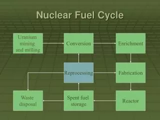
Main Hoist Analytical Model Upper Bridge Lower Bridge SFP Hoist Upper Rail Lower Rail & Wheel Power Center Motor Lower Rail & Wheel
Analytical Model - Inputs • Design Drawings • Boundary Conditions • Material and Sectional Properties of Structural Components • Proper member releases at bolted connections • Response Spectra for the SSE Event • Create analytical model using Structural Analysis Computer Code such as GTStrudl
Hoist & Hook Model Configurations N Main Hoist at Mid Span, SFP Hoist at North End. Main Hoist at North End, SFP Hoist at South End. Main Hoist at North End, SFP Hoist at Mid Span.
Acceptance Criteria and Codes • Plant Design Specification & Response Spectra • AISC Manual of Steel Construction, Allowable Stress Design • ASME NOG-1, Rules for Construction of Overhead and Gantry Cranes • ASME B&PVC Code, Section III, Division 1, Sub-Section NF • CMAA-70, Crane Manufacturers Association of America, “Specifications for Top Running Bridge & Gantry Type Multiple Girder Electric Overhead Traveling Cranes”
Service Condition • Analyzed for all service loads without seismic excitation and qualified per CMAA-70 • Loadings shall include Inertia of mass loads from movement of Crane, Trolley, Hoist, and Lifted Load • Loadings due to Wind, Skewing, Collision, Platform, and maximum critical hook loads shall be considered when applicable.
Seismic Condition • Analyzed for all normal operation deadweight loads acting simultaneously with seismic excitation from Safe Shutdown Earthquake (SSE) • Response spectrum method shall be used • Proper Combination of modes of seismic vibration • Proper Combination of directional seismic responses • Proper Damping factors
Special Modeling Technique • Sliding or rolling must be considered to prevent overturning • Force required to cause sliding or rolling must be calculated • Each crane drive wheel is restrained in the movement direction with a specified spring stiffness • The spring stiffness is derived by iteration • An initial stiffness is assumed; the value is changed & analysis rerun until the wheel seismic load equals the sliding/rolling force.
Required Crane Evaluations Primary Evaluations: Wheel Reactions, Displacements, Accelerations, Structural Steel Stresses, Plate Element Stresses Secondary Evaluations: Welds, Beam Connection Plates, Beam Flange/Web Deformations, Stiffener Plates, Bolts, and Wire Ropes
Some Typical Items Being Evaluated THE END TUBE ON TUBE CONNECTION M SHAPE TO W SHAPE CONNECTION
Bolt Evaluations • The maximum forces and moments for each connection type can be extracted from GTStrudl • 30-40 types of major bolted connections in the FHM • Can be grouped in 10-15 typical connection types • Each connection type has a different bolted configuration pattern due to size, number, and spacing of bolts • Each configuration has different sectional properties required for calculating max shear and tension stresses • Bolts must be qualified to applicable code
Slack Rope Evaluations • If the lifted load has an upward seismic acceleration greater than 1 g, the hoist wire rope may need to be evaluated for the slack rope condition • ASME NOG-1 provides design guidance for performing this evaluation • The maximum slack rope allowable is based on a percentage of the rope breaking strength • A non-linear time history analysis is normally required for performing the slack rope analysis • The analysis is only used for evaluating the rope for the most probable lifted load condition
Structural Analysis of a Nuclear Fuel Handling Machine THE END