Download
1 / 45
500 likes | 852 Views
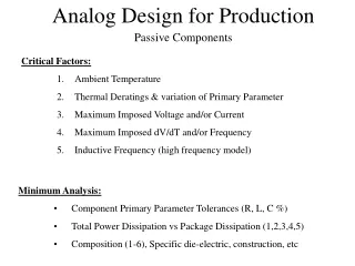
Lecture 16 Physical Design and Layout of Passive Analog Components. Michael L. Bushnell CAIP Center and WINLAB ECE Dept., Rutgers U., Piscataway, NJ. Resistor physical design Capacitor physical design Inductor physical design Summary. Resistors. Undoped polysilicon is highly resistive

E N D
Lecture 16Physical Design and Layout of Passive Analog Components Michael L. Bushnell CAIP Center and WINLAB ECE Dept., Rutgers U., Piscataway, NJ • Resistor physical design • Capacitor physical design • Inductor physical design • Summary Analog and Low-Power Design Lecture 16 (c) 2003
Resistors • Undoped polysilicon is highly resistive • Avoid doping the poly if you are making an R • Can get tera W (1012W ) resistors • Mixed-Signal applications • Use nichrome metal (NiCr) to make R’s • Laser trimming evaporates parts of the resistor while measuring R until it comes within specifications • R in KW / range • Excellent temperature stability & long-term reliability • Note that all R’s in circuit contribute thermal noise Analog and Low-Power Design Lecture 16 (c) 2003
Resistor Fabrication and Physical Design • Black lines show path of laser trimming beam Analog and Low-Power Design Lecture 16 (c) 2003
Resistor Fabrication Methods • Doped polysilicon – most useful R = 20 to 30 W / • Silicon process problem – R tolerances & matching • Clad-poly process: Silicide block mask needed to get sufficient R • Can withstand 100 V between R and substrate • Can operate beyond VSS to VDD range Analog and Low-Power Design Lecture 16 (c) 2003
Resistor Thermal Problems • Field oxide isolates R thermally • If R dissipates moderate to large power, get permanent R changes due to self-induced annealing • Poly can melt or crack due to heat, but very good for making fuses • Polysilicon R undesirable for Electro-Static Discharge protection Analog and Low-Power Design Lecture 16 (c) 2003
n Substrate Diffusion Resistor • Strip of n+ diffusion: R = 30 to 50 W / • Avalanche breakdown limits voltage to 10 to 15 V Analog and Low-Power Design Lecture 16 (c) 2003
p Substrate Diffusion Resistor • Must bias well above the resistor voltage to maintain isolation • Connect well to more positive R end or to VDD • Have limited R and low breakdown voltage • Strip of n-well contacts at either end of R • Put n substrate diffusion under contacts – prevents formation of rectifying Schottky barrier Analog and Low-Power Design Lecture 16 (c) 2003
p Substrate Resistor Problems • Notoriously variable resistors • Slight doping differences • Out-diffusion • Voltage modulation of depletion regions • Surface effects Analog and Low-Power Design Lecture 16 (c) 2003
Capacitor Issues • Want most C for least area • Fringing C now is very significant – use to get more C • Best capacitive coefficient: Cgs (gate to substrate MOS C) • 2nd Best: Cjap (p diffusion area) • 3rd Best: Cjp (n & p diffusion periphery) • 4th Best: Cjan (n diffusion area) • 5th Best: Cm1p (metal 1 to poly C) & Cm1d (metal 1 to diffusion) • 6th Best: Cp (poly over field oxide) and Cm2m1 (metal2 – metal1) Analog and Low-Power Design Lecture 16 (c) 2003
More Capacitor Issues • 7th Best: • Cm1(metal 1 over field oxide) • Cm2p (metal 2 to poly) • Cm2d (metal 2 to diffusion) • Cm3m2(metal 3 to Metal 2) • Problems with C’s coupled to substrate: one terminal is constrained • Do not use except when it suits the circuit • Use fringing C now – is more significant than substrate capacitance Analog and Low-Power Design Lecture 16 (c) 2003
Multi-Dimensional Capacitance Metal 3 Metal 2 Metal 1 • Used to get more C/unit area of chip surface than would be otherwise possible Analog and Low-Power Design Lecture 16 (c) 2003
Polysilicon Capacitor • ONO – oxide-nitride-oxide dielectric Analog and Low-Power Design Lecture 16 (c) 2003
Trench Polysilicon Capacitors • Trench C – Used for 64 Mbit DRAM 90 fF Analog and Low-Power Design Lecture 16 (c) 2003
Fin Capacitor • Fin C – Also used for 64 Mbit DRAM 20 to 30 fF Analog and Low-Power Design Lecture 16 (c) 2003
Capacitance Calculation • Cja = junction C / mm2 Cjp = periphery C / mm • a = diffusion width b = diffusion length • Sidewall C facing channel reduced by channel depletion region & absence of field implant • As we scale, peripheral C becomes more important • Cja& Cjp are f (junction voltage) • Cj = Cj0 (1 - ) –m Cj0 = zero-bias C • Vj = junction voltage Vb = built-in potential (0.6 V) • 0.3 (graded junction) m 0.5 (abrupt junction) Vj Vb Analog and Low-Power Design Lecture 16 (c) 2003
Scaling Effects on Capacitance • Increasing fringing fields increase C – add Cgs0, Cgd0, Cgb0 to Cgs, Cgd, Cgbfor SPICE • Caused by poly extension beyond channel & other overlaps • Transistor gate C – about 4 to 5 X diffusion C – dominates CL Analog and Low-Power Design Lecture 16 (c) 2003
Fringing Capacitance • Fringing field C • Approximate routing capacitance between metal & poly wires and substrate as a parallel plate C Analog and Low-Power Design Lecture 16 (c) 2003
Fringing Field Capacitance • Fringing fields increase effective plate area • Use C = A / h • In order to handle fringing, use: • w = conductor width h = insulator thickness • t = conductor thickness = insulator permittivity Analog and Low-Power Design Lecture 16 (c) 2003
Multiple Conductor Capacitance • With 3 to 5 routing layers, accurate C computation takes too long. Use formulae instead • Model of Metal 1 – 3 layers Analog and Low-Power Design Lecture 16 (c) 2003
Detailed Multiple Conductor Model • 3 Potential layers: • Top ground plane • Interesting conductor • Bottom ground plane Analog and Low-Power Design Lecture 16 (c) 2003
Multi-Layer Capacitances Analog and Low-Power Design Lecture 16 (c) 2003
Middle Layer Capacitance • Interesting conductor C has 3 components: • Line-to-ground C • Line-to-line C • Crossover C • Capacitance of middle layer to ground: • C2 = C21 + C23 + C22 • C21 & C23 – crossover C formula (for wires on top of each other) • C22 is line-to-line C – weighted sum Analog and Low-Power Design Lecture 16 (c) 2003
Middle Layer Capacitance (cont’d) • C22 = AC (line-to-line, 2 ground) + BC (line-to-line, isolated) • A + B = 1 • A = R , B = O (P1 + P3) (P1 + P3) W1 – W3 = layer 1-3 widths C/e = Normalized C per unit conductor length S1 - S3 = Layer 1-3 spacing between parallel wires = Dielectric permittivity of SiO2 T1 -- T3 = Layer 1-3 conductor thickness H = Thickness of dielectric between conductors R = Measure of ground plane coverage Analog and Low-Power Design Lecture 16 (c) 2003
Middle Layer Capacitance (cont’d) • Line-to-ground C with 1 Ground Plane: (4.19) Analog and Low-Power Design Lecture 16 (c) 2003
Middle Layer Capacitance (concl.) • O = Measure of space and hence capacitance to ground plane • Line-to-ground C with 2 Ground Planes: (4.20) Analog and Low-Power Design Lecture 16 (c) 2003
Middle Layer Capacitance (cont’d) • Line-to-line C with 1 Ground Plane: • Line-to-line C with 2 Ground Planes: (4.21) (4.22) Analog and Low-Power Design Lecture 16 (c) 2003
Crossover Capacitance • Valid range for formulae: 0.3 T/H 10 • 0.3 W/H 10; 0.3 S/H 10 Analog and Low-Power Design Lecture 16 (c) 2003
Process Characteristics • Thicknesses of layers: • Thinox 200 Metal1 6000 • Field-oxide 6000 M1-M2 Oxide 6000 • Poly 3000 Metal 2 12000 • M1-poly-oxide 6000 Passivation 20000 • Passivation put over entire chip (except pads) to chemically isolate it from the environment. • Above formulae give C / per unit conductor length Analog and Low-Power Design Lecture 16 (c) 2003
Method of Getting Lumped C C • Lumped C = ( ) X SiO2 X conductor length Analog and Low-Power Design Lecture 16 (c) 2003
Capacitance – Spacing Relationship Analog and Low-Power Design Lecture 16 (c) 2003
Layout Etching Conditions • C calculations must use actual etched layer dimensions on chip, not drawn dimensions • Example: Metal wire drawn 1mm wide but is etched at 0.75 mm • Use worst-case values: Max width & thinnest dielectric to compute RC delay & power • Use min. width & thickest dielectric to calculate gate race conditions Analog and Low-Power Design Lecture 16 (c) 2003
Crosstalk Claim • Mole claim: • As interconnections & circuitry scale down, cross-talk capacitance decreases • Reason: Required interconnect length decreases while cross-talk C / unit length varies little. • Holds for analog circuits, not necessarily true for digital Analog and Low-Power Design Lecture 16 (c) 2003
Capacitors • One plate poly, one plate diffusion (usually n-well) Analog and Low-Power Design Lecture 16 (c) 2003
Poly + Diffusion C • 0.5 to 1.6 fF / mm2 • Tolerances: 20% (only if well kept 1 V above poly voltage) • Problems: • Excessive bottom-plate parasitic junction series resistance • Non-linearity effects at some voltages Analog and Low-Power Design Lecture 16 (c) 2003
Inductors • Need a GHz Voltage-Controlled oscillator in sub-micron CMOS • Choices where phase noise inversely related to power consumption: • Ring oscillator – • Phase noise L {Dw} ~ kT R2, gm = 1 / R • Oscillator based on resonant f of LC tank • Active Inductor Phase noise L{Dw} ~ kT 2, gm = 2 w C w Dw ) ( w Dw ( ) 2 w C Analog and Low-Power Design Lecture 16 (c) 2003
Inductors (continued) • Oscillator based on resonant f of LC tank • Passive Inductor Phase noise proportional to power consumption: L{Dw} ~ kT R 2, gm = R (w C)2 • Must make R (series resistance of LC loop) as small as possible • Inductor options: • Spiral inductor on Si substrate • High substrate losses – limit Q factor of filter due to induced substrate currents w Dw ( ) Analog and Low-Power Design Lecture 16 (c) 2003
Inductors (continued) Q factor f or w • Solution: etch substrate away underneath inductor • Requires extra etching step after normal IC processing • Not allowed for normal mass production (Roufourgan & Raol and Roufourgan & Abidi) Analog and Low-Power Design Lecture 16 (c) 2003
Bond Wire Inductors • Use a bond wire inductance for extremely low phase noise • Bond wire parasitic L = 1 nH / mm, very low series R • Form 2 L’s, using 4 bond wires • Phase noise = -115 dBc / Hz • Offset frequency: 200 kHz from 1.8 GHz carrier • Power consumption: 8 mA at 3 V • Bond wire L not characterized for yield in mass production – industry is reluctant to use this method Analog and Low-Power Design Lecture 16 (c) 2003
Bond Wire Inductors Analog and Low-Power Design Lecture 16 (c) 2003
Recommended Inductor • Use a spiral coil on Si substrate without modifications • Bipolar technologies have no substrate losses, due to a high R substrate • Sub-micron CMOS – doped substrate leads to large currents induced in substrate & high losses • Needs careful optimization of coil design • Use 2 metal layers • Hollow spiral inductor • Power consumption = 6 mW • Phase noise L{Dw} = -116 dBc / Hz at 600 KHz offset from 1.8 GHz carrier Analog and Low-Power Design Lecture 16 (c) 2003
Hollow Spiral Inductors Analog and Low-Power Design Lecture 16 (c) 2003
Inductor Problems in RF Circuits • Present-day systems use off-chip C & L devices • Too expensive to make on-chip L • Q factor not high enough for cellular telephones • Use off-chip ceramic core inductors (cheap and very precise) • Q factor of L on chip at 1 GHz went from Q 3 to Q 6 over last 10 years • Noise-to-carrier (N/C) ratios vary as much as 20 dB at 100 kHz offset Analog and Low-Power Design Lecture 16 (c) 2003
More Spiral Inductor Problems • Generalized Impedance: Z • If one end grounded, really get: Z = R || || sL • R = series resistance of winding • L = what we want • C = capacitance between metal wire & substrate • Under-etching the inductor defeats C, but you still get R 1 sC Analog and Low-Power Design Lecture 16 (c) 2003
Prof. Lu’s Inductor (Rutgers) • Defeat C in on-chip spiral inductor by: • Using polyimide insulator with better • Make multiple layers of inductors on top of chip Analog and Low-Power Design Lecture 16 (c) 2003
Summary Analog physical design is important: • Resistors – use a variety of design shapes, each allowing laser trimming • Capacitors – use fringing capacitance to get higher values • Inductors – substrate eddy currents limit effectiveness • Need to under-etch Analog and Low-Power Design Lecture 16 (c) 2003