Download
1 / 12
250 likes | 721 Views
MAGNETIC EFFECT OF CURRENT - I. Magnetic Effect of Current – Oersted’s Experiment Ampere’s Swimming Rule Maxwell’s Cork Screw Rule Right Hand Thumb Rule Biot – Savart’s Law Magnetic Field due to Infinitely Long Straight Current – carrying Conductor

E N D
MAGNETIC EFFECT OF CURRENT - I • Magnetic Effect of Current – Oersted’s Experiment • Ampere’s Swimming Rule • Maxwell’s Cork Screw Rule • Right Hand Thumb Rule • Biot – Savart’s Law • Magnetic Field due to Infinitely Long Straight Current – carrying Conductor • Magnetic Field due to a Circular Loop carrying current • Magnetic Field due to a Solenoid Created by Arun Kumar., PGT(PHY),KV2-COLABA,Mumbai
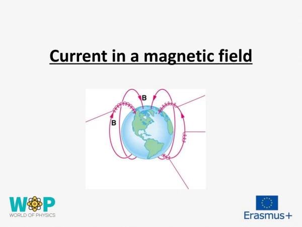
N N E I I K K E Magnetic Effect of Current: An electric current (i.e. flow of electric charge) produces magnetic effect in the space around the conductor called strength of Magnetic field or simply Magnetic field. Oersted’s Experiment: When current was allowed to flow through a wire placed parallel to the axis of a magnetic needle kept directly below the wire, the needle was found to deflect from its normal position. When current was reversed through the wire, the needle was found to deflect in the opposite direction to the earlier case.
W N N I S I I B B Rules to determine the direction of magnetic field: Ampere’s Swimming Rule: Imagining a man who swims in the direction of current from south to north facing a magnetic needle kept under him such that current enters his feet then the North pole of the needle will deflect towards his left hand, i.e. towards West. Maxwell’s Cork Screw Rule or Right Hand Screw Rule: If the forward motion of an imaginary right handed screw is in the direction of the current through a linear conductor, then the direction of rotation of the screw gives the direction of the magnetic lines of force around the conductor.
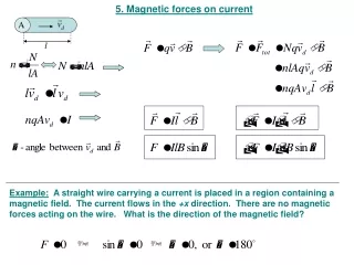
I B r θ dl I I dl sin θ dBα μ0 I dl sin θ x r2 dB= 4πr2 Right Hand Thumb Rule or Curl Rule: If a current carrying conductor is imagined to be held in the right hand such that the thumb points in the direction of the current, then the tips of the fingers encircling the conductor will give the direction of the magnetic lines of force. Biot – Savart’s Law: The strength of magnetic field dB due to a small current element dl carrying a current I at a point P distant r from the element is directly proportional to I, dl, sin θ and inversely proportional to the square of the distance (r2) where θ is the angle between dl and r. P i) dB αI ii) dB αdl iii) dB αsin θ iv) dB α 1 / r2 P’
μ0 I dl x r dB= 4πr2 μ0 I dl x r dB= 4πr3 x Biot – Savart’s Law in vector form: Value of μ0 = 4π x 10-7 Tm A-1 or Wb m-1 A-1 Direction of dB is same as that of direction of dl x r which can be determined by Right Hand Screw Rule. It is emerging at P’ and entering at P into the plane of the diagram. Current element is a vector quantity whose magnitude is the vector product of current and length of small element having the direction of the flow of current. ( I dl)
μ0 I dl sin θ dB= 4πr2 I Ф2 B Ф l θ Ф1 r dl μ0 I cos Ф dФ x dB= μ0 I cos Ф dФ Ф2 4π a μ0 I (sin Ф1 + sin Ф2) B = ∫dB =∫ B= 4π a -Ф1 4πa Magnetic Field due to a Straight Wire carrying current: According to Biot – Savart’s law sin θ = a / r = cos Ф or r = a / cos Ф tan Ф= l / a or l = a tan Ф dl = a sec2Ф dФ Substituting for r and dl in dB, a P Magnetic field due to whole conductor is obtained by integrating with limits - Ф1 to Ф2. ( Ф1 is taken negative since it is anticlockwise)
B μ0 2I μ0 I B= B= a a 0 2πa 4πa Direction of B is same as that of direction of dl x r which can be determined by Right Hand Screw Rule. It is perpendicular to the plane of the diagram and entering into the plane at P. I I B B If the straight wire is infinitely long, then Ф1 = Ф2 = π / 2 or Magnetic Field Lines:
dl dB dB C dB cosФ X Y 90° r Ф a Ф dB sinФ O Ф x dB sinФ I I Ф X’ Y’ dl dB cosФ D Magnetic Field due to a Circular Loop carrying current: 1) At a point on the axial line: P The plane of the coil is considered perpendicular to the plane of the diagram such that the direction of magnetic field can be visualized on the plane of the diagram. At C and D current elements XY and X’Y’ are considered such that current at C emerges out and at D enters into the plane of the diagram.
The angle θ between dland r is 90° because the radius of the loop is very small and since sin 90° = 1 μ0 I dl sin θ The semi-vertical angle made by r to the loop is Ф and the angle between r and dB is 90° . Therefore, the angle between vertical axis and dB is also Ф. dB= 4πr2 dB is resolved into components dB cosФand dB sinФ . Due to diametrically opposite current elements,cosФcomponents are always opposite to each other and hence they cancel out each other. SinФ components due to all current elements dl get added up along the same direction (in the direction away from the loop). μ0 I dl dB= 4π r2 μ0 I dlsinФ μ0 I (2πa) a B = ∫dB sin Ф=∫ B = μ0 I a2 4π r2 4π (a2 + x2) (a2 + x2)½ B = 2(a2 + x2)3/2 or or (μ0 , I, a,sinФare constants,∫dl = 2πa and r & sinФare replaced with measurable and constant values.)
B μ0 I a2 B = x x 0 2 x3 I B B B I I I μ0 I B = 2a Special Cases: i) At the centre O, x = 0. ii) If the observation point is far away from the coil, then a << x. So, a2 can be neglected in comparison with x2. Different views of direction of current and magnetic field due to circular loop of a coil:
a I dB 90° μ0 I dl sin θ O dB= 4π a2 I μ0 I dl dB= 4π a2 μ0 I dl B = ∫dB =∫ 4π a2 dl B x a 0 μ0 I B = 2a 2) B at the centre of the loop: The plane of the coil is lying on the plane of the diagram and the direction of current is clockwise such that the direction of magnetic field is perpendicular and into the plane. The angle θ between dland a is 90° because the radius of the loop is very small and since sin 90° = 1 (μ0 , I, a are constants and ∫dl = 2πa )
x x x x x x x B I I Magnetic Field due to a Solenoid: TIP: When we look at any end of the coil carrying current, if the current is in anti-clockwise direction then that end of coil behaves like North Pole and if the current is in clockwise direction then that end of the coil behaves like South Pole.