Download
1 / 12
150 likes | 415 Views
MT411 Robotic Engineering. Chapter 2 Introduction to Robotic System. Asian Institution of Technology (AIT). Narong Aphiratsakun, D.Eng. Robot.

E N D
MT411Robotic Engineering Chapter 2 Introduction to Robotic System Asian Institution of Technology (AIT) Narong Aphiratsakun, D.Eng
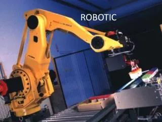
Robot Robot is essentially a mechanism are operating under computer control. A Robot is a reprogrammable, multifunctional manipulator designed to move material, parts, tools, or specialized devices through variable programmed motions for the performance of a variety tasks. An official definition of such Robot comes from the Robot Institute of America (RIA). Robots are widely used in industries. They are becoming more effective-faster, more accurate, and more flexible. They become able to do more and more tasks that might be dangerous or impossible for human workers to perform.
Industries Applications • Welding (dangerous) • Assembly (accuracy and high speed) • Car assembly (large force, high speed and dangerous)
Symbolic Representation Robot manipulators are composed of links connected by joints to form a kinematic chain. Each joint represents the interconnection between two links. Joints are typically rotary (R: revolute) or linear (P:prismatic).
Geometry Most industrial manipulators at the present time have 6 or fewer degree of freedom (DOF). The number of DOF is equal to the dimension of the configuration space. The number of joints determines the number of DOF. A manipulator should posses at least six independent DOF (3 for positioning and 3 for orientation). With fewer than 6 DOF, the arm cannot reach every point in its work space. A manipulator having more than 6 DOF is referred to as a kinematic ally redundant (exceeding what is necessary) manipulator. • These manipulators are usually classified on the basis of the first three joints of the arm (the wrist being described separately). There are five geometric types. Each of these five manipulator arms is a serial link robot. • RRR : articulated. • RRP : spherical. • RRP: SCARA. • RPP : cylindrical. • PPP: cartesian.
RRR : Articulated This articulated manipulator is called anthropomorphic manipulator. The three links are designated as the body, upper arm, and forearm, respectively. The joints axes are designated as the waist (z0), shoulder (z1) and elbow (z2). The joint axis z2 is parallel to z1 and both z1 and z2 are perpendicular to z0. The ABB IRB1400 articulated arm is shown in Figure.
RRP : Spherical This spherical manipulator is replacing the elbow joint in the revolute by a prismatic joint. The joints axes are designated as z0 perpendicular to z1 and z1 is perpendicular to z2. The Stanford Arm is an example of a spherical manipulator.
RRP : SCARA This SCARA (Selective Compliant Articulated Robot for Assembly) manipulator is very popular manipulator for assembly operations. The joints axes are designated as z0 , z1 and z2 mutually parallel. The Epson E2L653S is an example of a SCARA manipulator.
RPP : Cylindrical This Cylindrical manipulator is often used in material transfer tasks. The joints axes are designated as z0 is revolute, while second and third joints are prismatic. The Seiko RT3300 is an example of a cylindrical manipulator.
PPP : Cartesian This Cartesian manipulator is useful for table-top assembly applications and transfer of material. The three joints are prismatic. The Epson Cartesian Robot is an example of a Cartesian manipulator.
Wrists and End Effectors The joint in the kinematic chain between the arm and end effector are referred to as the waist. Wrist center point is the common point where three joints axes intersect. Wrist can have 1,2 or 3 DOF depending on application.
Wrists and End Effectors The arm and waist of a robot are used primarily for positioning the end effector. The end effector (tool) is actually performs the tasks such as handling, gripping, welding, assembly, grinding, etc.