Download
1 / 34
340 likes | 447 Views
Learn about sequential circuits, state machines, finite state machines, memory elements, clock circuits, and more in digital logic design. Explore the differences between combinational and sequential logic. Master the implementation of finite state machines.

E N D
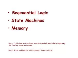
Seqeuential Logic • State Machines • Memory Note: I did clean up the slides from last period, particularly improving the FlipFlop transition tables. Note: About making past midterms and finals available.
4 1 8 4 30 25 5 20 10 15 Combinational vs. Sequential Logic • There are two types of “combination” locks Combinational: Success depends only onthevalues, not the order in which they are set. Sequential: Success depends onthesequenceof values (e.g, R-13, L-22, R-3).
State Machine • A type of sequential circuit • Combines combinational logic with storage • “Remembers” state, and changes output (and state) based oninputsandcurrent state State Machine Inputs Outputs Combinational Logic Circuit Storage Elements • A Mealy machine has outputs that depend on the state and input • A Moore machine has outputs that depend on state only
Finite State Machine • A description of a system with the following components: • A finite number of states • A finite number of external inputs • A finite number of external outputs • An explicit specification of all state transitions • An explicit specification of what determines each external output value • Often described by a state diagram. - The set of all possible states. - Inputs that trigger state transitions. - Outputs associated with each state (or with each transition).
State Diagram • Showsstates (e.g. A) andactions (e.g. R-13) that cause atransitionbetween states.
State • The state of a system is a snapshot of all the relevant elements of the system at the moment the snapshot is taken. • Examples: • The state of a basketball game can be represented bythe scoreboard. (Number of points, time remaining, possession, etc.) • The state of a tic-tac-toe game can be represented bythe placement of X’s and O’s on the board.
State of Sequential Lock Our lock example has four different states, labelled A-D:A: The lock isnot open,and no relevant operations have been performed. B: The lock isnot open,and the user has completed the R-13 operation. C: The lock isnot open,and the user has completedR-13, followed by L-22. D: The lock isopen.
State Diagram • Showsstates (e.g. A) andactions (e.g. R-13) that cause atransitionbetween states.
The Clock • Frequently, a clock circuit triggers transition fromone state to the next. • At the beginning of each clock cycle, the state machine makes a transition, based on the current state and the external inputs (Synchronous). • Not always required. In lock example, the input itself triggers a transition (Asynchronous). “1” “0” One Cycle time
Implementing a Finite State Machine • Combinational logic • Determine outputs at each state. • Determine next state. • Storage elements • Maintain state representation. State Machine Inputs Outputs Combinational Logic Circuit Storage Elements Clock
Storage • Each master-slave flipflop stores one state bit. • The number of storage elements (flipflops) neededis determined by the number of states(and the representation of each state). • Examples: • Sequential lock • Four states – two bits • Basketball scoreboard • 7 bits for each score digit, 5 bits for minutes, 6 bits for seconds,1 bit for possession arrow, 1 bit for half, …
22 x 3 Memory word select word WE input bits address write enable address decoder output bits
Memory Design – 1K x 4 A[09:00] D[03:00] Addr Block Select
Memory Design – 1K x 8 D[07:04] D[03:00] A[09:00] A[09:00] D[07:04] D[03:00] Addr BlockSelect => Addr Block Select =>
Memory Design - 2k x 8 D[07:04] D[03:00] Block 01 Block 00
D[07:04] D[03:00] Memory Design - 4k x 8 Block 11 Block 10 Block 01 Block 00
More Memory Details Two basic kinds of RAM (Random Access Memory) • Static RAM (SRAM) • fast, maintains data as long as power applied • Dynamic RAM (DRAM) • slower but denser, bit storage decays – must be periodically refreshed. Refreshing interferes with regularity of execution of instruction stream. Also, non-volatile memories: ROM, PROM, flash, …
Some Major Advances in Computers in 50 years • VLSI • The family concept • Microprogrammed control unit • Cache memory • MiniComputers • Microprocessors • Pipelining • PC’s • Multiple processors • RISC processors • Hand helds
Three Classes of Today’s Computer Architectures • CISC – Complex Instruction Set Computer • RISC – Reduced Instruction Set Computer • Superscalar – Multiple similar processing units are used to execute instructions in parallel
Driving force for CISC • Software costs far exceed hardware costs • Increasingly complex high level languages • A “Semantic” gap between HHL & ML • This Leads to: • Large instruction sets • More addressing modes • Hardware implementations of HLL statements • e.g. CASE (switch) on VAX (long, complex structure)
Intention of CISC • Ease compiler writing • Improve execution efficiency • Support more complex HLLs
RISC • Reduced Instruction Set Computer • Key features: • Large number of general purpose registers (or use of compiler technology to optimize register use) • Limited and simple instruction set • Emphasis on optimising the instruction pipeline & memory management
The debate: Why CISC ? • Compiler simplification? • Dispute… - Complex machine instructions are harder to exploit - Optimization actually may be more difficult • Smaller programs? (Memory is now cheap) • Programs may take up less instructions, but… • May not occupy less memory, just look shorter in symbolic form • More instructions require longer op-codes, more memory references • Register references require fewer bits
The Debate: Why CISC ? • Faster programs ? • More complex control unit • Microprogram control store larger • Thus instructions may take longer to execute • Instructions are not of consistent length and take different lengths of time to complete. • Legacy challenges
Controversy Continued: CISC vs RISC Challenges of comparison • There are no pair of RISC and CISC that are directly comparable • There are no definitive set of test programs • It is difficult to separate hardware effects from complier effects • Most comparisons are done on “toy” rather than production machines • Most commercial machines are a mixture
Concentrating on RISC: Major Characteristics: • One instruction per cycle • Register to register operations • Few, simple addressing modes • Few, simple instruction formats Also: • Hardwired design (no microcode) • Fixed instruction format But: • More compile time/effort
Early RISC Computers • MIPS – Microprocessor without Interlocked Pipeline Stages Stanford (John Hennessy) MIPS Technology • SPARC – Scalable Processor Architecture Berkeley (David Patterson) Sun Microsystems • 801 – IBM Research (George Radin)