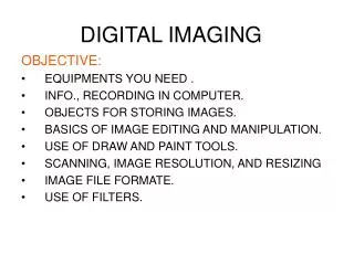
Digital Imaging
Digital Imaging. CHAPTERS 1, 4-7 CARTER. CHAPTER 1. Conventional radiography Film/screen system Light exposes film Film processed with chemicals Film taken to radiologist for interpretation. Let’s compare rooms for. Conventional (Film) CR DR. Let’s compare image formation/acquisition.


Digital Imaging
E N D
Presentation Transcript
Digital Imaging CHAPTERS 1, 4-7 CARTER
CHAPTER 1 • Conventional radiography • Film/screen system • Light exposes film • Film processed with chemicals • Film taken to radiologist for interpretation
Let’s compare rooms for • Conventional (Film) • CR • DR
Let’s compare image formation/acquisition • Film • CR • DR
Let’s compare image processing • Film • CR • DR
IP layers Protective Phosphor/active Reflective Conductive Color Support Backing barcode Protects phosphor PSP-barium fluorohalide Sends light forward when released in the reader Absorbs/reduces static electricity Absorb stimulating light (laser)/reflects emitted light Protects the back of cassette Match image with patient CR- Chapter 4
Reading the IP • Red laser light scans in a raster pattern at 2 eV • Laser scans multiple times as IP moves through reader =translation • Light produced –detected by photomultiplier
DIGITIZING • PHOSPHOR STORAGE CENTER IS SCANNED • RELEASED ELECTRON ENTER DIGITIZER DIVIDES THE ANALOG SIGNAL INTO SQUARES (MATRIX). • EACH SQUARE IS ASSIGNED A NUMBER BASED ON THE BRIGHTNESS OF THE SQUARE • SQUARE IS CALLED A PIXEL
SPATIAL RESOLUTION • Film screen = 10 line pairs per mm • CR =2.55 to 5 line pairs per mm (lp/mm) • Less detail in CR but more tissue densities seen given the appearance of better detail • Wider dynamic recording range
speed • Film – determined by size and layers of crystals and phosphors • CR – amount of photostimulable luminescence given off = 100 film speed screen (approx)
EXPOSURE –CASSETTE BASED-chapter 5 • What is the relationship between selecting the correct body part and computer interpretation of the image? • Too much kVp (above 120) and too little (below 45) can over excite or produce too little excitation of the phosphors • Does the pixel size of a 2000 x 2000 matrix change when using an 8 X10 vs a 14 x 17 CRcassette? • How does the change in pixel size impact resolution?
MOIRE PATTERN • Grid lines from a stationary grid can cause a wavy artifact known as a moire pattern. The grid lines and the scanning laser run parallel
Exposure Indicators • Exposure indicator number • Fuji, Philips, Konica – S number-indirect relationship • Kodak –Exposure index (EI)-direct relationship • Page 88 tables 5-1 and 5-2
HISTOGRAM • Graphic representation of the numerical tone (grays/blacks/whites) of an x-ray exposure • More when we move on to Chapter 7
OTHER ARTIFACTS • Plate artifacts • Adhesive tape residue • cracks • Plate reader artifacts • Line patterns • Plate reader loads multiple IP in one cassette • Image processing artifacts • Incorrect erasure (ghosting) • moire • Printer artifacts • White lines
CASSETTELESS -Chapter 6 • Direct and indirect • DR plate (amorphous selenium) or(a-Se)-converts radiation into an electrical signal –CCD or silicon detectors • Signal stored in a Thin film transmitter (TFT)
Two step process X-rays convert to light Light converted to electrical signal Sent to TFT X-rays converted directly to an electrical signal Sent to TFT INDIRECT DIRECT
DQE • Detective Quantum Efficiency • Ability to convert an x-ray signal into a useful image • Of the following-which do you think has the most efficient DQE? • Film or CR or indirect capture DR or direct capture DR?
Digital Radiographic Image Processing and Manipulation Chapter 7
CR image *sampling (*conversion from analog to digital) • Histogram • X axis = amount of exposure(number of grays) • Y axis = number of pixels for each exposure • Low kVp= wider histogram???? • High kVp = narrower histogram??? • Histogram is anatomy specific
histogram http://bloggingradiography.blogspot.com/2007/08/anatomy-of-histogram.html
NYQUIST THEOREM • When sampling(converting from analog to digital) a signal, the sampling frequency must be greater than the bandwidth of the input signal • http://images.google.com/imgres?imgurl=http://www.cs.cf.ac.uk/Dave/Multimedia/nyquist.gif&imgrefurl=http://www.cs.cf.ac.uk/Dave/Multimedia/node149.html&h=420&w=529&sz=6&hl=en&start=10&um=1&tbnid=zyDOLJNUH6mM8M:&tbnh=105&tbnw=132&prev=/images%3Fq%3Dnyquist%
http://www.pcguide.com/art/soundSampleRate-c.html Sample? Try this at home
ALIASING • When the spatial frequency is greater than the Nyquist frequency and the sampling occurs less than twice per cycle, information is lost causing a moire effect.
Automatic Rescaling • Fixing the image • Why is this dangerous?
LUT and Windowing • Automatic rescaling to achieve appropriate contrast on an image • http://www.sprawls.org/resources/DIGPROCESS/module.htm#13
LATITUDE • Find the percentage the exposure can be greater or less than before it impacts the image in CR
IMAGE MANIPULATION cont. • Window- how light or dark an image should be • Level-contrast • Background removal or shuttering • Removing the unexposed borders or to blacken the white borders
MTF • Modular Transfer function • Reproducing the spatial resolution of an object as a diagnostic image • 100% of the spatial resolution of the object can never be perfectly reproduced – even with DR and CR – why? -See Bushong – pgs 451-454
PSP CRT ADC IP CR DR PACS SNR CNR 10. CCD 11. FOV 12. LUT 13. DICOM 14. RIS 15. HIS 16. TFT 17. DQE acronyms
Photostimulable phosphor-europian activated barium fluorohalide • Cathode-ray tube or computer monitor • Analog to digital converter • Imaging plate • computed • /digital radiography • Picture archiving communication systems
SIGNAL TO NOISE RATIO PG 410 –BUSHONG The higher the signal the less the noise. • CONTRAST TO NOISE RATIO can be manipulated until noise becomes too apparent-limited by the SNR • Charge coupled device- crystal silicon- small, replaces vidicon in fluoro, device used in DR • Field of View –how much of the patient is imaged in the matrix • Look up Table – plotting grays on a scale • Digital imaging and communications in medicine -blending PACS and other imaging modalities • Radiology Information system • Hospital Information system
Thin Film Transmitters- indirect and direct conversion detector in DR. Stores electronic charge (from converted light) before computer processes it. • Detective Quantum Efficiency converting x-ray intensities into a radiographic image