Overview of Pipelining Principles and Processor Design Techniques
This chapter delves into the fundamental concepts of pipelining in processor design, including an overview of the SRC architecture, pipeline hazards, and instruction-level parallelism (ILP). It discusses the principles of superscalar processors and Very Long Instruction Word (VLIW) machines, as well as the microprogramming aspects involved in control store and micro-branching. The chapter also outlines the five stages of the pipeline, emphasizing the challenges of dependency among instructions and the solutions such as pipeline stalling, data forwarding, branch delay slots, and load delays.

Overview of Pipelining Principles and Processor Design Techniques
E N D
Presentation Transcript
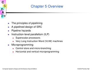
Chapter 5 Overview • The principles of pipelining • A pipelined design of SRC • Pipeline hazards • Instruction-level parallelism (ILP) • Superscalar processors • Very Long Instruction Word (VLIW) machines • Microprogramming • Control store and micro-branching • Horizontal and vertical microprogramming
Fig 5.1 Executing Machine Instructions vs. Manufacturing Small Parts
The Pipeline Stages • 5 pipeline stages are shown • 1. Fetch instruction • 2. Fetch operands • 3. ALU operation • 4. Memory access • 5. Register write • 5 instructions are executing • shr r3, r3, 2 ;storing result in r3 • sub r2, r5, r1 ;idle, no mem. access needed • add r4, r3, r2 ;adding in ALU • st r4, addr1 ;accessing r4 and addr1 • ld r2, addr2 ;instruction being fetched
Notes on Pipelining Instruction Processing • Pipeline stages are shown top to bottom in order traversed by one instruction • Instructions listed in order they are fetched • Order of insts. in pipeline is reverse of listed • If each stage takes one clock: - every instruction takes 5 clocks to complete - some instruction completes every clock tick • Two performance issues: instruction latency, and instruction bandwidth
Dependence Among Instructions • Execution of some instructions can depend on the completion of others in the pipeline • One solution is to “stall” the pipeline • early stages stop while later ones complete processing • Dependences involving registers can be detected and data “forwarded” to instruction needing it, without waiting for register write • Dependence involving memory is harder and is sometimes addressed by restricting the way the instruction set is used • “Branch delay slot” is example of such a restriction • “Load delay” is another example
Branch and Load Delay Examples Branch Delay • Working of instructions not changed, but way they work together is brz r2, r3 add r6, r7, r8 st r6, addr1 This inst. always executed Only done if r3 0 Load Delay ld r2, addr add r5, r1, r2 shr r1,r1,4 sub r6, r8, r2 This inst. gets “old” value of r2 This inst. gets r2 value loaded from addr
Characteristics of Pipelined Processor Design • Main memory must operate in one cycle • This can be accomplished by expensive memory, but • It is usually done with cache, to be discussed in Chap. 7 • Instruction and data memory must appear separate • Harvard architecture has separate instruction & data memories • Again, this is usually done with separate caches • Few buses are used • Most connections are point to point • Some few-way multiplexers are used • Data is latched (stored in temporary registers) at each pipeline stage—called “pipeline registers.” • ALU operations take only 1 clock (esp. shift)
Adapting Instructions to Pipelined Execution • All instructions must fit into a common pipeline stage structure • We use a 5 stage pipeline for the SRC 1) Instruction fetch 2) Decode and operand access 3) ALU operations 4) Data memory access 5) Register write • We must fit load/store, ALU, and branch instructions into this pattern
Fig 5.2 ALU Instructions fit into 5 Stages • Second ALU operand comes either from a register or instruction register c2 field • Op code must be available in stage 3 to tell ALU what to do • Result register, ra, is written in stage 5 • No memory operation
Fig 5.4 Load and Store Instructions • ALU computes effective addresses • Stage 4 does read or write • Result reg. written only on load
Fig 5.6 SRC Pipeline Registers and RTN Specification • The pipeline registers pass info. from stage to stage • RTN specifies output reg. values in terms of input reg. values for stage • Discuss RTN at each stage on blackboard
Global State of the Pipelined SRC • PC, the general registers, instruction memory, and data memory is the global machine state • PC is accessed in stage 1 (& stage 2 on branch) • Instruction memory is accessed in stage 1 • General registers are read in stage 2 and written in stage 5 • Data memory is only accessed in stage 4
Restrictions on Access to Global State by Pipeline • We see why separate instruction and data memories (or caches) are needed • When a load or store accesses data memory in stage 4, stage 1 is accessing an instruction • Thus two memory accesses occur simultaneously • Two operands may be needed from registers in stage 2 while another instruction is writing a result register in stage 5 • Thus as far as the registers are concerned, 2 reads and a write happen simultaneously • Increment of PC in stage 1 must be overridden by a successful branch in stage 2
Fig 5.7 Pipeline Data Path & Control Signals • Most control signals shown and given values • Multiplexer control is stressed in this figure
Example of Propagation of Instructions Through Pipe 100: add r4, r6, r8; R[4] R[6] + R[8]; 104: ld r7, 128(r5); R[7] M[R[5]+128]; 108: brl r9, r11, 001; PC R[11]: R[9] PC; 112: str r12, 32; M[PC+32] R[12]; . . . . . . 512: sub ... next instruction • It is assumed that R[11] contains 512 when the brl instruction is executed • R[6] = 4 and R[8] = 5 are the add operands • R[5] =16 for the ld and R[12] = 23 for the str
Fig 5.8 Cycle 1 add Enters Pipe • Program counter is incremented to 104 512: sub ... . . . . . . 112: str r12, #32 108: brl r9, r11, 001 104: ld r7, r5, #128 100: add r4, r6, r8
Fig 5.9 Cycle 2ld Enters Pipe • add operands are fetched in stage 2 512: sub ... . . . . . . 112: str r12, #32 108: brl r9, r11, 001 104: ld r7, r5, #128 100: add r4, r6, r8
Fig 5.10 Cycle 3 brl Enters Pipe • add performs its arithmetic in stage 3 512: sub ... . . . . . . 112: str r12, #32 108: brl r9, r11, 001 104: ld r7, r5, #128 100: add r4, r6, r8
Fig 5.11 Cycle 4str enters pipe • add is idle in stage 4 • Success of brl changes program counter to 512 512: sub ... . . . . . . 112: str r12, #32 108: brl r9, r11, 001 104: ld r7, r5, #128 100: add r4, r6, r8
Fig 5.12 Cycle 5 sub Enters Pipe • add completes in stage 5 • sub is fetched from loc. 512 after successful brl 512: sub ... . . . . . . 112: str r12, #32 108: brl r9, r11, 001 104: ld r7, r5, #128 100: add r4, r6, r8
Functions of the SRC Pipeline Stages • Stage 1: fetches instruction • PC incremented or replaced by successful branch in stage 2 • Stage 2: decodes inst. and gets operands • Load or store gets operands for address computation • Store gets register value to be stored as 3rd operand • ALU operation gets 2 registers or register and constant • Stage 3: performs ALU operation • Calculates effective address or does arithmetic/logic • May pass through link PC or value to be stored in mem.
Functions of the SRC Pipeline Stages (continued) • Stage 4: accesses data memory • Passes Z4 to Z5 unchanged for non-memory instructions • Load fills Z5 from memory • Store uses address from Z4 and data from MD4(no longer needed) • Stage 5: writes result register • Z5 contains value to be written, which can be ALU result, effective address, PC link value, or fetched data • ra field always specifies result register in SRC
Dependence Between Instructions in Pipe: Hazards • Instructions that occupy the pipeline together are being executed in parallel • This leads to the problem of instruction dependence, well known in parallel processing • The basic problem is that an instruction depends on the result of a previously issued instruction that is not yet complete • Two categories of hazards Data hazards: incorrect use of old and new data Branch hazards: fetch of wrong instruction on a change in PC
General Classification of Data Hazards(Not Specific to SRC) • A read after write hazard (RAW) arises from a flow dependence, where an instruction uses data produced by a previous one • A write after read hazard (WAR) comes from an anti-dependence, where an instruction writes a new value over one that is still needed by a previous instruction • A write after write hazard (WAW) comes from an output dependence, where two parallel instructions write the same register and must do it in the order in which they were issued
Detecting Hazards and Dependence Distance • To detect hazards, pairs of instructions must be considered • Data is normally available after being written to reg. • Can be made available for forwarding as early as the stage where it is produced • Stage 3 output for ALU results, stage 4 for mem. fetch • Operands normally needed in stage 2 • Can be received from forwarding as late as the stage in which they are used • Stage 3 for ALU operands and address modifiers, stage 4 for stored register, stage 2 for branch target
Data Hazards in SRC • Since all data memory access occurs in stage 4, memory writes and reads are sequential and give rise to no hazards • Since all registers are written in the last stage, WAW and WAR hazards do not occur • Two writes always occur in the order issued, and a write always follows a previously issued read • SRC hazards on register data are limited to RAW hazards coming from flow dependence • Values are written into registers at the end of stage 5 but may be needed by a following instruction at the beginning of stage 2
Possible Solutions to the Register Data Hazard Problem • Detection: • The machine manual could list rules specifying that a dependent instruction cannot be issued less than a given number of steps after the one on which it depends • This is usually too restrictive • Since the operation and operands are known at each stage, dependence on a following stage can be detected • Correction: • The dependent instruction can be “stalled” and those ahead of it in the pipeline allowed to complete • Result can be “forwarded” to a following inst. in a previous stage without waiting to be written into its register • Preferred SRC design will use detection, forwarding and stalling only when unavoidable
RAW, WAW, and WAR Hazards • RAW hazards are due to causality: one cannot use a value before it has been produced. • WAW and WAR hazards can only occur when instructions are executed in parallel or out of order. • Not possible in SRC. • Are only due to the fact that registers have the same name. • Can be fixed by renaming one of the registers or by delaying the updating of a register until the appropriate value has been produced.
Tbl 5.1 Instruction Pair Hazard Interaction Write to Reg. File Result Normally/Earliest available • Latest needed stage 3 for store is based on address modifier register. The stored value is not needed until stage 4 • Store also needs an operand from ra. See Text Tbl 5. • Instruction separation is used rather than bubbles because of the applicability to multi-issue, multi-pipelined machines. Read from Reg. File Class alu load ladr brl N/E 6/4 6/5 6/4 6/2 Class N/L alu 2/3 load 2/3 ladr 2/3 store 2/3 branch 2/2 Value Normally/ Latest needed 4/1 4/2 4/1 4/1 4/1 4/2 4/1 4/1 4/1 4/2 4/1 4/1 4/1 4/2 4/1 4/1 4/2 4/3 4/2 4/1 Instruction separation to eliminate hazard, Normal/Forwarded
Delays Unavoidable by Forwarding • In the column headed by load, we see the value loaded cannot be available to the next instruction, even with forwarding • Can restrict compiler not to put a dependent instruction in the next position after a load (next 2 positions if the dependent instruction is a branch) • Target register cannot be forwarded to branch from the immediately preceding instruction • Code is restricted so that branch target must not be changed by instruction preceding branch (previous 2 instructions if loaded from mem.) • Do not confuse this with the branch delay slot, which is a dependence of instruction fetch on branch, not a dependence of branch on something else
Stalling the Pipeline on Hazard Detection • Assuming hazard detection, the pipeline can be stalled by inhibiting earlier stage operation and allowing later stages to proceed • A simple way to inhibit a stage is a pause signal that turns off the clock to that stage so none of its output registers are changed • If stages 1 & 2, say, are paused, then something must be delivered to stage 3 so the rest of the pipeline can be cleared • Insertion of nop into the pipeline is an obvious choice
Fig 5.14 Stall Due to a Dependence Between Two alu Instructions
Restrictions Left If Forwarding Done Wherever Possible br r4 add . . . • • • ld r4, 4(r5) nop neg r6, r4 ld r0, 1000 nop nop br r0 not r0, r1 nop br r0 • 1) Branch delay slot • The instruction after a branch is always executed, whether the branch succeeds or not. • 2) Load delay slot • A register loaded from memory cannot be used as an operand in the next instruction. • A register loaded from memory cannot be used as a branch target for the next two instructions. • 3) Branch target • Result register of alu or ladr instruction cannot be used as branch target by the next instruction.
Instruction Level Parallelism • A pipeline that is full of useful instructions completes at most one every clock cycle Sometimes called the Flynn limit • If there are multiple function units and multiple instructions have been fetched, then it is possible to start several at once • Two approaches are: superscalar • Dynamically issue as many prefetched instructions to idle function units as possible • and Very Long Instruction Word (VLIW) • Statically compile long instruction words with many operations in a word, each for a different function unit • Word size may be 128 or 256 or more bits.
Character of the Function Units in Multiple Issue Machines • There may be different types of function units • Floating point • Integer • Branch • There can be more than one of the same type • Each function unit is itself pipelined • Branches become more of a problem • There are fewer clock cycles between branches • Branch units try to predict branch direction • Instructions at branch target may be prefetched, and even executed speculatively, in hopes the branch goes that way
Microprogramming: Basic Idea • Recall control sequence for 1-bus SRC • Control unit job is to generate the sequence of control signals • How about building a computer to do this? Step Concrete RTN Control Sequence T0. MA PC: C PC+4; PCout, MAin, Inc4, Cin, Read T1. MD M[MA]: PC C; Cout, PCin, Wait T2. IR MD; MDout, IRin T3. A R[rb]; Grb, Rout, Ain T4. C A + R[rc]; Grc, Rout, ADD, Cin T5. R[ra] C; Cout, Gra, Rin, End
The Microcode Engine • A computer to generate control signals is much simpler than an ordinary computer • At the simplest, it just reads the control signals in order from a read only memory • The memory is called the control store • A control store word, or microinstruction, contains a bit pattern telling which control signals are true in a specific step • The major issue is determining the order in which microinstructions are read
Fig 5.22 Block Diagram of a Microcoded Control Unit • Microinstruction has branch control, branch address, and control signal fields • Micro-program counter can be set from several sources to do the required sequencing
Parts of the Microprogrammed Control Unit • Since the control signals are just read from memory, the main function is sequencing • This is reflected in the several ways the PC can be loaded • Output of incrementer—PC+1 • PLA output—start address for a macroinstruction • Branch address from instruction • External source—say for exception or reset • Micro conditional branches can depend on condition codes, data path state, external signals, etc.
Contents of a Microinstruction • Main component is list of 1/0 control signal values • There is a branch address in the control store • There are branch control bits to determine when to use the branch address and when to use PC+1
Figure 5.23: Layout of the Control Store • Common inst. fetch sequence • Separate sequences for each (macro) instruction • Wide words
Horizontal Versus Vertical Microcode Schemes • In horizontal microcode, each control signal is represented by a bit in the instruction • In vertical microcode, a set of true control signals is represented by a shorter code • The name horizontal implies fewer control store words of more bits per word • Vertical code only allows RTs in a step for which there is a vertical instruction code • Thus vertical code may take more control store words of fewer bits
Fig 5.25 A Somewhat Vertical Encoding • Scheme would save (16+7) - (4+3) = 16 bits/word in the case illustrated
Saving Control Store Bits With Horizontal Microcode • Some control signals cannot possibly be true at the same time • One and only one ALU function can be selected • Only one register out gate can be true with a single bus • Memory read and write cannot be true at the same step • A set of m such signals can be encoded using log2m bits (log2(m+1) to allow for no signal true) • The raw control signals can then be generated by a k to 2k decoder, where 2k ≥ m (or 2k ≥ m+1) • This is a compromise between horizontal and vertical encoding