Download
1 / 1
10 likes | 184 Views
Vacuum Tube Audio Amplifier. Matt Andrews, Yuriy Kharin Adviser: Dr. Michael J. Carter. Why Vacuum Tubes? Very linear even when driven in saturation region(smooth c lipping) Can be used in very high voltage circuits

E N D
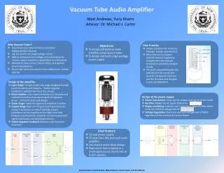
Vacuum Tube Audio Amplifier Matt Andrews, YuriyKharin Adviser: Dr. Michael J. Carter • Why Vacuum Tubes? • Very linear even when driven in saturation region(smooth clipping) • Can be used in very high voltage circuits • Able to withstand over-voltage and overheating for minutes where transistors would blow in milliseconds • Believed to have a more natural, fuller, and warmer sound reproduction. • Even order harmonics which is less offensive to human hearing • How it works: • 4 Main components: Filament, Cathode, Anode, and the Grid • When filament is heated, cathode releases negatively charged electrons that get attracted to positively charged Anode • The grid is located between the cathode and the anode and controls the flow of electrons just like the base and the gate in BJTs and MOSFETS • Objectives: • To design and build an audio amplifier using vacuum tubes • To design and build a high wattage power supply • Design of the amplifier: • Input Stage: Simple single tube stage designed for high input resistance and linearity. Global negative feedback is applied here from the output. • Phase Splitter: Uses matched resistors at the plate and cathode to produce two equal signals of opposite phase. Critical for push pull design. • Driver Stage: Takes the signal and amplifies it further. • Output Stage: High current gain and implements an output transformer to match the high output impedance of the amplifier to the eight ohm load. Employs potentiometer networks to ensure equal grid signal amplitudes and operating currents. • Global Negative Feedback: Reduces total harmonic distortion • Design of the power supply: • Power Transformer: Steps up the voltage coming out of the outlet • Rectifier: Makes the AC signal all positive • Ripple smoothing: Inductor and 2 capacitors form a Pi filter which turns the rectified voltage into DC • Voltage Regulation: Maintains constant voltage level of 360V regardless of the amount of current drawn • Final Product: • 72 watt power supply. • 25 watt Class AB1 push pull audio amplifier. • Two chassis mono-block design. • Plays music from a laptop or a small signal source clearly into an 8 ohm speaker. Special thanks to Adam Perkins, Mike Andrews, Lincoln Lavoie, and Tom Merrick