Download

1 / 18
190 likes | 352 Views
Wave Imaging Technology Inc. PSDM for “Easy” Unconventional Reservoirs? Morgan Brown Rocky Mountain Section, AAPG September 10, 2012. Why Wave Equation PSDM?. Simple refraction. Air. Kirchhoff. WEM. RTM. Water. Complex focusing. Niobrara Shale Case Study.

E N D
Wave Imaging Technology Inc. PSDM for “Easy” Unconventional Reservoirs? Morgan Brown Rocky Mountain Section, AAPG September 10, 2012
Why Wave Equation PSDM? Simple refraction Air Kirchhoff WEM RTM Water Complex focusing
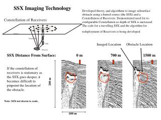
Niobrara Shale Case Study • Hi-res 50 sq mi 3D, Laramie Co., WY • 200 fold, Wide azimuth • Part 1: PSDM Structural Imaging • Success = Velocity • Improved event geometry, fault imaging • Part 2: PSDM “Sweet Spot” Delineation • Azimuthal anisotropy • AVAZ
Part 1: Improved Structural Imaging X X PSDM PSTM T Z
Shallow Low-Velocity Wedge Starting velocity model, derived from PSTM velocities Final velocity model after 8 updates • The difference between theory and practice is greater in practice than in theory • Theory: PSDM should always beat PSTM • Practice: PSTM often won • Why? PSDM is very sensitive to velocity • Saved by Computer Power! • Automated picking • Multiple iterations X Y Z Velocity (ft/sec)
Angle Gathers: PSTM Velocity Angle (deg) Angle (deg) X Y Z
Angle Gathers: Optimized Velocity Angle (deg) Angle (deg) X Y Z
PSTM: Location 1 X Y T X Y T
PSDM: Location 1 Converted to Time X Y T X Y T
Part 2: Sweet Spot Delineation • Complex Earth offset is NOT angle • Ideal attributes • With real angle gathers • In depth offset Simple earth Complex earth q q
PSDM Azimuth Angle Gathers x y fast Azimuth (deg) slow Fracture Schematic Y X Z 0 90
Azimuth Angle Gathers (flattened) x y fast Azimuth (deg) slow Fracture Schematic Y X Z 0 90
Fracture (Horizontal Stress) Map ~0.3% Quandary: Target is naturally fractured, but overburden is apparently not. Are the reflection amplitudes (versus azimuth) at the target sensitive to fracturing? N FMI ~0.1% E
AVA + Azimuth = AVAZ • WEM Incidence vs. Azimuth angle gathers • For each azimuth, compute AVA slope • Make “fracture” map from AVA slope vs. azimuth using Rüger analysis • More apparent sensitivity to fractures in target zone
From AVAZ Slope ~5% N FMI ~50% E
AVAZ Sensitivity (Rüger, 1998) Takeaway: realistic parameter assumptions produce 50% AVAZ variation • Assumptions for most sensitive parameters: • gbot = 0.05 • gtop= 0.0 • dbot= 0.01 • dtop= 0.0 • VP-VS ratio = 2 above and below
Takeaways • Part 1 • PSDM: • Removes false time structures • Better positions/focuses steep dips and faults • High-intensity velocity analysis = PSDM success • Part 2 • WEM angle gathers: attributes in complex geology • Azimuthal anisotropy was weak here • AVAZ analysis appears more sensitive and targeted
Acknowledgements • Fidelity E&P, JD Rockies Resources (Itochu Oil) • At Fidelity: Dave List, Chris Lang, Patrick Rutty • The WIT Team: Joe Higginbotham, Cosmin Macesanu, Oscar Ramirez, Cathy Joanne