Download
1 / 32
320 likes | 421 Views
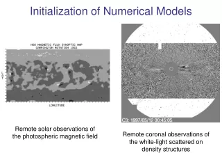
Explore field line behavior in 3D reconnection through analytical and numerical models. Review key publications and findings, including properties, kinematic reconnection, numerical simulations, and experimental setups. Discuss new properties in 3D reconnection and the importance of parallel electric fields. Conclude with insights on magnetic flux evolution and qualitative agreements with models.

E N D
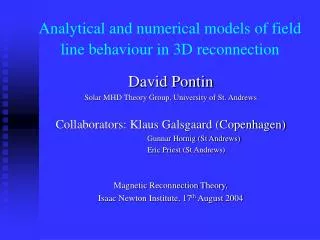
Analytical and numerical models of field line behaviour in 3D reconnection David Pontin Solar MHD Theory Group, University of St. Andrews Collaborators: Klaus Galsgaard (Copenhagen) Gunnar Hornig (St Andrews) Eric Priest (St Andrews) Magnetic Reconnection Theory, Isaac Newton Institute, 17th August 2004
Overview • Review: properties of 3D kinematic rec. See: • Priest, E.R., G. Hornig and D.I. Pontin, On the nature of three-dimensional magnetic reconnection, J. Geophys. Res., 108, A7, SSH6 1-8, 2003. • G. Hornig and E.R. Priest, Evolution of magnetic flux in an isolated reconnection process, Physics of Plasmas10(7), 2712-2721 (2003) • Pontin, D. I., G. Hornig and E. R. Priest, Kinematic reconnection at a magnetic null point: Spine-aligned current, Geophys. Astrophys. Fluid Dynamics, in press (2004a) • Pontin, D. I., G. Hornig and E. R. Priest, Kinematic reconnection at a magnetic null point: Fan-aligned current, Geophys. Astrophys. Fluid Dynamics, submitted (2004b) motivating…… • Numerical simulation on 3D reconnection in the absence of a magnetic null (work in progress!!)
Bline velocity w, s.t. Bline mapping not continuous: break in diffusion region at X-point only. 1-1 correspondence of reconnecting Blines and flux tubes. 2D Reconnection: basic properties
in general now s.t. Blines followed through D do not move at voutside D. Blines continually change their connections in D. 3D Rec.: No w for isolated non-ideal region (D)
Analytical examples • Solve kinematic steady resistive MHD eq.s: Resistive Ohm’s law Maxwell’s eq.s; t-independent • Impose B, then deduce E,v. • Assume localised
rec Impose Source of rotation: consider pot. drop round loop Diffusion region Counter-rotating flows
Flux tube rec: Splitting and flipping, no rejoining of flux tubes
New properties to look for in dynamical numerical expt: • Blines split immediately on entering non-ideal region (D). • Blines continually & continuously change connections in D. • : mismatching • Counter-rotating flows above and below D. • Non-existence of perfectly-reconnecting Blines.
Numerical Experiment • Code: HPF • Eqs. • Staggered grids: b.c., f.c., e.c. • 6th order derivative algorithm (+ 5th order interp.) • 3rd order predictor-corrector in time • BCs dealt with using ghost zones, periodic b.c.`s in 2 dir.s & driven in other
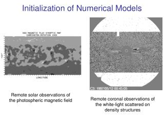
Initial setup • : two flux patches on top and bottom, rotated w.r.t. each other + background Calculate potential field in domain Driving on boundaries moves patches to joining lines; sinusoidal profile
B in domain • in volume ‘hyperbolic flux tube’ • 2D X-pt, uni-dir. comp. • Generalisation of separator intersection of 2 QSLs • Topologically simple • Geometrically complex • Twist induces strong V.S. Titov, K. Galsgaard and T. Neukirch, Astrophys. J.582, 1172-1189, 2003. K. Galsgaard, V.S. Titovand T. Neukirch,Astrophys. J.595, 506-516, 2003.
Different expts. Cold plasma / full MHD 1. Fixed localised resistivity: 2. `Anomalous resistivity’, dep on J
Induced plasma velocity • Stagnation pt. v in central plane: • `Pinching’ • Also have up/down flow ~1/3 of strength • Strong outflows suggest rec.
Induced Current (central plane) • concentration, centred on axis, grows steadily. • `Wings’ mark outflow jets remains well resolved
Behaviour of lines • Following circular X-sections of Blines in inflow:
-flowlines • Choose Blines initially joined & follow from both ends. Paths of intersections with central plane. cf. Blines split on entering D. Flow lines coloured to show speed.
Rot flows • w maps similar to kin. solns: background rot? • Calc above/below D sign agrees with kinematic model for J dir
Importance of Parallel Electric Field • v. important for Bline rec Flow lines coloured with movie
Importance of Parallel Electric Field II • Surface of in central plane. • Profile of along selection of Blines Localisation in plane elongated along conc. Struc simple- monotonic decay away from O
Expt 2 • Initial/boundary cond.s same • = 1.5 / 2.5 / 3.5
J • As before, but wings develop only when rec. delayed until system sufficiently stressed. • Width of J conc same as before
Non-ideal regions Isosurf.s of at 25% of max: Fixed Switch-on
v • Stag flow, but jets only develop later • up/down flow marks J wings • large extent in plane • rot flows still present- also larger extent
Bline rec • pattern of rec similar • not as well localised along B
w-flows • region of w-splitting & squashed & stretched • Nature of mis-matching same
Conclusions • Shows rec in HFT • Full MHD simulation- qualitative agreement with kinematic model for rec. • rotational flows • nature of w mis-matching • Qualitatively similar for fixed/`anomalous’ • Bline rec continual & continuous in non-id region • Flux evolution requires TWO Bline velocities
Null rec: spine • Induced plasma flow rotational: • Blines rec. in `shells’ • Source of rot. flows
Flux tube rec.: J parallel to spine • Add ideal stag. flow to see global effect • Tubes split entering D, flip, but do not rejoin. • No v across spine/fan
Null rec: fan has different signs for x +ve / -ve. So unidirectional across fan. across fan, opposite sign for y +ve / -ve
Flux tube rec.: J parallel to fan Plasma crosses spine and fan Split, flip, no rejoin. Flux transported across fan at finite rate.
Results so far • Confirmed: • splitting of lines on entering non-ideal region • continual reconnection in non-ideal region: non-existence of unique Bline velocity • existence of rot flows • Importance of parallel electric field for process, simple structure of profile.