DSP Design Lab Solutions for Efficient Implementation Results
200 likes | 302 Views
Explore the implementation results and techniques used in DSP design labs to achieve optimal performance. Important aspects like clock buffers, multipliers, and timing constraints are discussed. Compare and analyze results for various lab exercises.

DSP Design Lab Solutions for Efficient Implementation Results
E N D
Presentation Transcript
Answers DSP Design Flow
Lab 1: Wrap up • Implementation results: 66 Slices, ~130 MHz • Important to notice: • Global clock buffer is automatically instantiated • Embedded multiplier is used by default in Virtex™-IIP devices. In this lab, the option was turned off in order to use slice-based multipliers • Timing constraint should always be used to achieve the performance required • XCF file must be generated manually • Remember size to compare with the other flows
Lab 2: Wrap up • Implementation results: 71 slices, 175 MHz • Important to notice: • Global clock buffer should be instantiated because the synthesis tool may not know which signal is the clock because it is looking at a black box
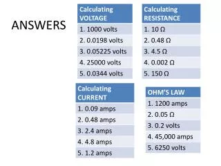
Module 2: Answers Using the technique shown, convert the following fractional values… • Define the format of the following twos complement binary fraction and calculate the value it represents • What format should be used to represent a signal that has: • Fill in the table: Format = < Fix_12_5 > 1 1 0 0 0 1 1 0 1 0 1 1 Value = -917 = -28.65625 32 c) Max value: 278 Min value: -138 Quantized to 11 bit data a) Max value: +1 Min value: -1 Quantized to 12 bit data b) Max value: 0.8 Min value: 0.2 Quantized to 10 bit data Format = < FIX _12_10 > Format = <UFIX_10_10> Format = < FIX _11_1>
Lab 3: Solution MAC using embedded multiplier Slice Count: 24 Slices, 1 embedded multiplier Performance: ~244 MHz(2vp4 -7) MAC using slice-based multiplier Slice Count: 69 Slices Performance: ~182 MHz(2vp4 -7) Multiplier Latency - 2
Module 3: Answers • How many clock cycles per input are required for a fully parallel 12-bit data, 20 tap symmetric filter? • Hardware over-sampling rate = 1 • The requirement for a filter is to run at 25 MSPS. A 100 MHz system clock is available on the board. What should the hardware over-sampling rate parameter be set to for 8-bit data? • Hardware over-sampling rate = 100/25 = 4 • How many clock cycles per input are necessary to process in serial an 11-bit data, 31 tap symmetric filter? • Hardware over-sampling rate = 11 + 1 = 12
Lab 4: Solution • 365 slices • Clock rate: 229 MHz • Sample rate: 229/9 = 25.4 MSPS
Lab 5: Solution Slices: 170 Clock Speed: ~211 MHz
Lab 6: Solution RTL View for Saturation and Rounding RTL View for Rounding
Module 5: What Values Do You Expect? Number Input Signed Data Truncate and Wrap Convert Reinterpret Slice Signed Data Output Binary point of 3 Total Number of Bits 3 Bottom of Slice offset by 5 from the LSB
Lab 7: Blocks-Based Solution • Post-Map Resource Estimates • Slices – 15 • FFs – 16 • LUTs – 28
Lab 7: MCode-Based Solution • Post-Map Resource Estimates • Slices – 16 • FFs – 16 • LUTs – 28 function done = term_cnt(count) if count == 183 done = true; else done = false; end
Block Gateway In antiAliasFIR antiAliasFIR1 Gateway Out Sample Period Sample Period (GCD) Module 7 Exercise: Audio Application • Analyze the following sampling rate change system that is commonly found in audio broadcasting studios. Determine the Simulink System Sample period: 7056 kHz 44.1 kHz 441 kHz 48 kHz DAT format CD format 1/44100 1/441000 1/7056000 1/48000 160/7056000 16/7056000 1/7056000 147/7056000 1/7056000 Simulink System Sample Period:
D D Q X y CE CE2 Q CE3 CK CE2 CE CE3 Answer: Audio Application 96 kHz 48 kHz 32 kHz DAB format DAT format Normalized Sample Times: 1 2 3 CE3 Sample Rate Control Logic CE CE CE2 System CLK System CE
Block Output Sample Normalized Frequency Sample Time InReg 48 kHz 2 Up Sampler 96 kHz 2 and 1 AntiAliasFIR 96 kHz 1 Down Sampler 32 kHz 1 and 3 OutReg 32 kHz 3 Answer: Audio Application
Module 7: Propagation in Loops Q. What would happen if a full precision adder is used in this example? An error will occur as an infinite loop will be created
Lab 8: Solution Slice Count: (Slice-based MULT) 126 slices Performance ~ 208 MHz Slice Count: (with MULT18x18) 89 slices Performance ~204 MHz