Download
1 / 14
180 likes | 538 Views
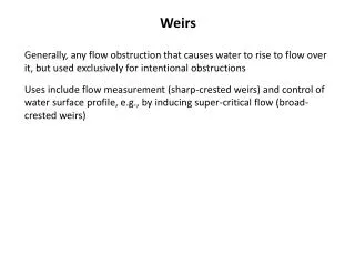
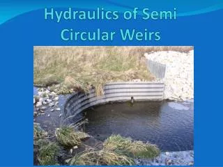
Hydraulics of Semi Circular Weirs. Hydraulics of Semi Circular Weirs. Q=CLH t 3/2 L = Effective Length of Weir H t = Total Head (Still Pool) = H + V 2 /2g = Energy Grade Line H & V measured 3H upstream from weir C = Weir Coefficient

E N D
Hydraulics of Semi Circular Weirs • Q=CLHt3/2 L = Effective Length of Weir Ht = Total Head (Still Pool) = H + V2/2g = Energy Grade Line H & V measured 3H upstream from weir C = Weir Coefficient Commonly used coefficient for these structures is 2.722.72????
Hydraulics of Semi Circular Weirs • C = Weir Coefficient • 1980 ASAE paper “Corrugated Aluminum Drop Structures for Erosion Control” by Blum (NRCS) & DeGraff (Kaiser Aluminum) states: • The basic C, 3.1, is modified to allow for freeboard, using SCS criteria of 3.1/1.14, or C = 2.72. • Kaiser Aluminum Structural Plate Drop Structures manual (DP-109 Edition 3) also specifies this C = 3.1 = 2.7 1.14Modification to allow for freeboard
Hydraulics of Semi Circular Weirs • Where does the 1.14 come from? NEH Section 11, Drop Spillways, p.3.7 - Freeboard
Hydraulics of Semi Circular Weirs • NEH Section 11, p.3.7 • … it is convenient and logical to consider freeboard in terms of increased weir discharge capacity. It also seems logical to assume that the required freeboard should be some function of the overfall through the drop spillway, F, since the possible damage due to failure increases with an increase in F. • Reasonable increase in discharge capacity= 0.10 + 0.01F= 0.10 + 0.01(4) Assuming a 4’ drop= 0.14
Hydraulics of Semi Circular Weirs • The use of a weir coefficient of 2.72 has nothing to do with a semi circular weir layout. It is just the traditional coefficient of 3.1 modified to provide freeboard.
Hydraulics of Semi Circular Weirs • Weir Control FlowQ = C1L(2g)1/2H3/2
Hydraulics of Semi Circular Weirs • Example • W = 20’ • L = 43.1’ • F = 4’ • B = 5.7’ • Wc = 24’ • Wc/L = .55 • →C1 = 0.21 • Q = 0.21*(2g)1/2*(H)3/2
Hydraulics of Semi Circular Weirs • Example • W = 20’ • L = 43.1’ • F = 4’ • B = 5.7’ • Wc = 35’ • Wc/L = 0.8 • →C1 = 0.34 • Q = 0.34*(2g)1/2*(H)3/2
Hydraulics of Semi Circular Weirs • Tailwater submergence effect also considered in Becker’s ASAE paper. • Too confusing to address today. • Jean Sandstrom (Des Moines, NRCS) is developing a standard drawing for the 6’ version of the drop. She also put together a spreadsheet to assist in hydraulic analysis. Still, a lot of table look ups