Binding
This presentation is intended to be viewed in slideshow mode. If you are reading this text, you are not in slide show mode. Hit the F5 function key to enter slideshow mode. Binding. Note: These slides are intended to be a supplement to the textbook, not a replacemen t. Roadmap.

Binding
E N D
Presentation Transcript
This presentation is intended to be viewed in slideshow mode. If you are reading this text, you are not in slide show mode. Hit the F5 function key to enter slideshow mode. Binding Note: These slides are intended to be a supplement to the textbook, not a replacement
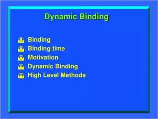
Roadmap • Main memory, addresses, and binding • Compiling, linking, and compile time binding • Load time binding • Execution time binding • Summary
Main Memory CPU+ • When the CPU wants to fetch data or an instruction from the main memory, it sends down the address it wants to read and sets the read/write line to ‘Read’ • Main memory then retrieves the content (bit pattern) stored in the requested address and transfers it up to the CPU • When the CPU wants to write data to the main memory, it sends down both the address and the data and sets the read/write line to ‘Write’ R W • Main memory is just a bunch of fixed length cells that hold the bit patterns that the CPU treats as data or instructions • All that matters to us in CS420 is the nature of an address • The address we see here, the address that actually shows up in the control circuits of memory, is called a physical address, since it physically controls the location in main memory which will get read or written • By definition, any address sent to main memory is a physical address address data read/write • Each cell has a unique address, very analogous to the house number in a snail mail address • For reasons that are quite irrelevant here, it’s customary to show addresses in hex 0x00x10x20x30x4 0x5 0x6 0x7 0x8 0x9 0xa • Memory then stores the data at the addressed location ⁞ ⁞ 0xffff mainmemory
Instruction Set Architecture (ISA), Instruction Decoding, and Addresses • The question is, when your program sends an address to main memory, where did that address come from? I.e., how and when was it generated, by what piece of software and/or hardware? • For our simple example here, let’s say that this instruction, the 32-bit pattern 0x3e700005, will be decoded by the CPU as follows: • The 3e will be the opcode which, for the purpose of our example here, will mean “read data from memory” • The 00005 will be the address of the data in memory that the CPU wants to read • The hex digit 7 will be a register designator, meaning that the data read from memory is to be placed in general purpose register #7 in the CPU CPU+ • Before we can answer that question, we need some concepts and vocabulary that come from the world of instruction set architecture (ISA) • Since we only need a few, simple concepts, we’ll look at a simple ISA • Unless you write your own machine language code, the 0x3e and the 0x7 came from the compiler or assembler that translated your code into machine language • But the 0x00005 almost certainly did not come from the compiler! • Why not? address data read/write 0x00x10x20x30x4 0x5 0x6 0x7 0x8 0x9 0xa • An instruction is just a bit pattern in memory • The ISA, which is determined by the computer’s designers, refers to, among other things, how the different bits are interpreted by the CPU hardware when it decodes the instruction after it has done its instruction fetch from memory into the CPU’s Instruction Register sometimes known, for obvious reasons, as the Instruction Decode Register • So our question now is, where did the various bit fields in the 0x3e700005 come from? some data to be read 0x3e700005 0x3e700005 ⁞ ⁞ 0xffff mainmemory
Binding • Reading that file, e.g., a.out, into memory is a completely separate activity (separate from compilation), performed by a program called the loader, that we’ll look at shortly • How can the compiler know where the program and its data will wind up in memory when your program actually executes? • The output from a compiler is included in a file on disk, perhaps a.out • So the compiler can’t put the 0x00005 here in this instruction, since it (the compiler) doesn’t normally know where in main memory your program will wind up • So what does get put here? And who puts it here? • The translation of logical addresses to physical addresses is called binding and it can occur at three different times: • Compile time (not very common) • Load time • Execution time • To understand the constraints on these various possible binding times, we need to look in a little more detail at the interactions among several OS utilities a.out 0x00x10x20x30x4 0x5 0x6 0x7 0x8 0x9 0xa some data to be read ????? 00002 0x3e7 • Answer to the first question: It’s a relative address (relative to the start of the code), an offset from the start of the code • A relative address is also known as a logical address some data to be read 2 0x3e700005 ⁞ ⁞ 0xffff mainmemory mainmemory
Roadmap • Main memory, addresses, and binding • Compilation, linking, loading, and compile time binding • Load time binding • Execution time binding • Summary
Compilation Produces Object Modules program1.o program1.c main gcc main myFunct1 • Each time it runs successfully, a compiler produces an output file, usually called an object module • An object module contains something very close to machine code for all the functions contained in the file being compiled myFunct1 myFunct2 myFunct2
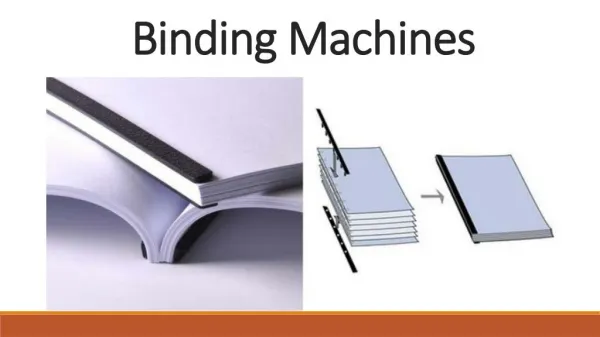
Linking object module libraries scanf printf scanf printf • There’s no reason that everybody who uses printf or scanf should have to re-compile it every time they re-compile their own C code, so most library functions are precompiled and stored in libraries as object modules program1.o a.out ld program1.c main main gcc • By default, gcc calls the linker after the compilation itself is done, so you need not explicitly call it (ld) yourself, although you can certainly use it manually if and when you need to • When compiling C, ld’s default is to delete your code’s object module after it (ld) is done preparing the load module on the disk (e.g., a.out) • There are options for you to instruct gcc and ld to keep your object modules around if you yourself want to use them later – you can even build your own object module libraries, if you wish main myFunct1 myFunct1 myFunct1 • A program called a “linker” is used to combine object modules from different compilation runs into a single load module stored on a disk, e.g., a.out • The standard Unix/Linux linker is named ld myFunct2 myFunct2 myFunct2
Linking, Unsatisfied Externals, Relative Addresses, and Compile Time Binding object module libraries … with their actual offsets from the start of the load module, their logical (or relative) addresses, in other words So here, for example, in our made up ISA, where we have an instruction in main calling the printf function … • If the programmer could tell the compiler, and hence the linker, the starting (or base) physical address in main memory where the code was going to be loaded, the linker could bind a relative address to a physical address by adding the logical address (offset) to the base address • That’s called compile time binding, but it’s not practical except on very small, single user systems • On a system designed to support multi-programming by multiple users, manual coordination of memory usage is not practical scanf printf • 0x2a ???? sample machine language op code for a CALLinstruction … it can replace all the symbolic externals … program1.o a.out ld • For a system of any real complexity, for which compile time binding is thus impractical: • Extra hardware in the form of a Memory Management Unit (MMU) can be added to the computer to provide execution time binding, we’ll look at an example in a few slides, but extra hardware obviously incurs extra costs • If there is no MMU for execution time binding, the logical addresses in the linker’s output will require load time binding by the OS loader ?? 0x5600 program1.c main main main scanf gcc Note that the compiler couldn’t possibly know exactly where the printf function was going to wind up in the final load module since, when compiling program1.c, the compiler has no way of knowing how big the separately compiled scanf module is nor where it will appear in the final load module it’s the linker’s job to find and assemble these things, not the compiler’s Instead, the compiler must somehow alert the linker to the fact that it (the linker) will have to later replace an “external” symbol (e.g., the symbolic name printf)with a relative address when it (the linker) figures out where in the final load module it will put the printf code main Once the linker figures out who goes where and how big each part is … printf myFunct1 myFunct1 myFunct1 ?? … the object module produced by the compiler couldn’t even include a relative address for the printf code, since even that (the offset, or relative address) isn’t known at compile time myFunct1 myFunct2 myFunct2 myFunct2 myFunct2 • 0x2a005600 • 0x2a printf
Roadmap • Main memory, addresses, and binding • Compilation, linking, loading, and compile time binding • Load time binding • Execution time binding • Summary
The Load Module • The output from the linker is a load module on disk (e.g., a.out) • A load module is sometimes, called an executable the Wikipedia article on the linker used to call it that(it still may) but that’s misleading: • It is not directly executable as is unless the hardware provides execution time binding (although most modern hardware does) • Otherwise, the OS must provide load time binding and the linker output can’t actually be executed until its logical addresses are bound to physical addresses by the loader • “Load module” is a better term than “executable”: If the hard-ware supports execution time binding, linker output is actually directly executable; but otherwise it’s not. Either way, the output is always a file on disk that is input to the loader; so it seems to me (and many others) that it’s better to call it a load module. • So unless we’re doing compile time binding, all the address references after linking can only be interpreted as offsets from the start of the load module, as logical addresses, in other words • E.g., in a load module, an instruction like 0x2a003fe8* would have to mean jump to (transfer control to, fetch the next instruction from) a location 0x3fe8bytes from the start of the code_____________ • *Remember, I just made up 0x2a as an example of the machine op code for a CALL instruction; the actual op code is dependent on the hardware’s ISA Remember: Unless told otherwise (compile time binding), neither the compiler nor the linker has any idea where in physical memory the program will ultimately get loaded for execution that’s the province of the loader and the OS memory management function a.out 0x3fe8 0x2a003fe8
Load Time Binding I.e, when it actually executes the CALL instruction, the CPU hardware must fetch the next instruction, the target of the CALL, from physical address 0x3004+0x3fe8 =0x6fec main memory • 0x0000 • 0x3004 • 0x6fec • When a process applies for admission, it must tell the long term scheduler how big a chunk of physically contiguous main memory it will need to execute in • Note that the size and relative locations of the functions or object modules inside the load module are irrelevant here, only the overall size matters in use a.out The start (base) physical address of that chunk is then given to the loader so it can load the module there from disk free 0x2a006fec 0x3fe8 If we are doing load time binding, once the load module is actually in memory, starting at physical address 0x3004 in this example, the logical address inside this instruction is no longer correct; it must be changed (bound) to the correct physical address, the 0x3004 base plus the 0x3fe8 offset from the base • The long term scheduler asks the memory manager if there’s enough space available for the new process • The memory manager searches the free space list (we’ll talk about this list later) to find a chunk of unused memory big enough to hold the load module 582K free 0x2a003fe8 No problem, you say; we’ll just have the loader add the base address of 0x3004 to every word of the load module as it is loaded; so here it would add 0x3004 to 0x3fe8 to get 0x6fec in use free in use free
Load Time Binding Must Be SelectiveNot Every Word Needs the Base Address Added main memory The CALL instruction gets its binding bit set; the ADDI doesn’t (and we don’t know the status of the other instructions in this picture since I didn’t make up code for them ;-) • 0x3004 in use • The problem is that not every instruction contains an address that needs to be bound • Depending on the ISA, a CALL instruction probably contains an address that needs binding, but there are probably other instructions that don’t contain addresses in the instructions • Here, for example, is an example of an ADDI instruction (Add Immediate), that contains, built in to the machine code itself, a constant, 1, in this case, that the program wants to add to some other number (think x++ in C); we certainly don’t want to add 0x3004 to that sample op code for an ADDI instruction … but ignores any constants that don’t Notice that the binding flags are not part of the executable image actually loaded into memory But the result is what we want: The loader uses those binding bits to tell it which instructions contain logical addresses that need binding… • 0x7f000001 ?????????????? ? 0x2a003fe8 • So some instructions in the load module contain addresses that need binding when the load module is loaded; some don’t • How is the poor loader supposed to know the difference? The solution is for the compiler, which certainly knows what type of instructions it’s generating, to add a flag to every instruction in every object module to indicate to the loader whether or not there’s a logical address in there that requires binding to a physical address ?? • 0x7f000001 • 0x7f000001 ????? 0x2a006fec 0x2a003fe8 in use in use binding bit
Summary of Compiling, Linking, and Loading • The compiler produces an object module which is usually not a complete program until it is combined with other, separately compiled, object modules • The linker combines (links) all the necessary object modules together into a single load module, resolving any symbolic external references the compiler left in any of the object modules • The loader is the OS software that actually moves the load module from the disk into the memory assigned by the OS memory manager when the process is admitted by the long term scheduler
Summary of Compile and Load Time Binding • For compile time binding: Programmers have to manually coordinate the starting addresses for their code so they can tell the compiler where in memory their code is supposed to start (how else would the compiler know?) so that it does not conflict with the code from other users; that’s not practical for multiprocessing systems • For load time binding: The loader needs a “bind me” bit (flag) for each word of the load module • Those flags are “extra” bits added by the compiler to the object code; not part of the code itself • They are passed through the linker into the load module • The loader uses them, but doesn’t move them into memory when it loads the load module. Where would they go? The ISA of the CPU hasn’t been designed to allow for them as part of an instruction; the loader is software designed long after the hardware has been designed and built
Roadmap • Main memory, addresses, and binding • Compilation, linking, loading, and compile time binding • Load time binding • Execution time binding • Summary
Execution Time Binding Requires Extra Hardware an MMU Memory Management Unit (MMU) main memory Base Address Register (BAR) physical address of the start (base) of the process in main memory the process physical address space in memory LA PA LA CPU + • Quiz questions: • The MMU BAR is part of the ??? of the running process • So when a process changes state to or from the running state, resetting the BAR is part of the ??? • When the process is not running, its BAR is stored in it’s ??? The Base Address Register of the MMU contains the starting (or base) physical address in main memory of the currently running process • The Memory Management Unit (MMU) is normally considered to be a separate piece of hardware that sits between the CPU and the main memory • Here we’ll look at a very simple MMU just to see how execution time binding works in general • Later, we’ll look at some much more interesting forms of execution time binding, requiring much more sophisticated MMU’s, and much more interaction with the operating system as well • With execution time binding, physical addresses never exist in the CPU • Every address emitted by the CPU is still just a logical address (LA) A logical address, of course, is just an offset relative to this base So the MMU binds the logical address to a physical address by simply adding the logical address to the base address The MMU then emits the physical address (PA) that the memory will actually read or write
Roadmap • Main memory, addresses, and binding • Compilation, linking, loading, and compile time binding • Load time binding • Execution time binding • Summary
Can We See the Difference Between Logical and Physical Addresses? • If we put a logic state analyzer on the address lines into memory, we could see if, when this instruction got executed, the physical address showing up to control the read from memory was the same as this one: • If they were the same, then memory would contain a physical address, which means it must have been bound at compile time (we know it wasn’t bound at load time, since this address in memory is the same as the address in the load module on the disk) • If they were different, then binding must have taken place after the CPU emitted this logical address at execution time main memory in use • If these two bit patterns are different, we know that we’re doing load time binding and the load module contains a logical address and the image in memory, the physical one (and the address in memory has to be bigger than the address on disk, no?) • But if they’re the same, we could have either already done the binding at compile time or be waiting for it to happen when this instruction is executed • Is there any way to tell the difference? • Not by looking at the bit patterns themselves, no, a bit pattern is just a bit pattern. But … a.out free 0x2a003fe8 free 0x2a003fe8 in use free in use free