Download

1 / 4
40 likes | 156 Views
This document provides operational instructions for the SFP Checker Version 3.20110427. It outlines the steps for connecting the device via USB, selecting COM port settings, and configuring error rate control. Instructions are provided on retrieving SFP module data including vendor name, part number, serial number, and wavelength using function keys. Additionally, it covers the use of the optical power meter and how to measure output power through the BERT process. Follow these steps for efficient operation and accurate readings.

E N D
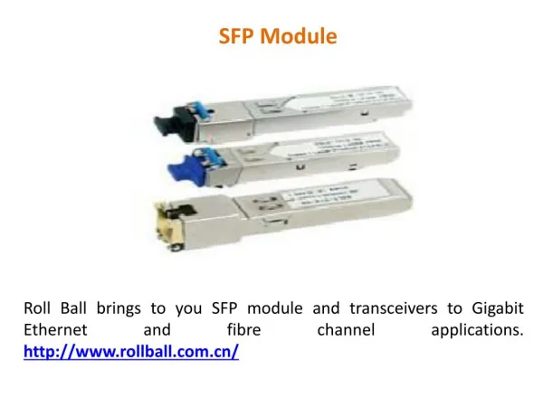
SFP Checker Operational Instructions Version:3.20110427
SFP Checker interface indication Function Key # 7 Selection # 1 Function Key # 8 Display # 4 Selection # 2 Function Key # 10 Function Key # 9 Display # 2 Function Key # 11 Display # 5 Display # 6
SFP Checker operational instructions: • 1. ComPort: Connect your Computer USB port to the SFP CHECKER . To Select Selection #1 ComPort and to click the Function Key #7OpenCom. • 2. CMU Rate Control: To Select the Selection #2 of Error Rate & Pattern. • 3. Error Rate data: It can be read Error Rate data through different datarate in Display #3. The Timer will be there a few adjustment according to datarate selected.
SFP Checker operational instructions: • 4. SFP module part no. data: Press Function Key #8SCAN ID can retrieve SFP module’s data, Vendor Name, Part Number, Serial Number and Wavelength. Press Function Key #9Start also could get the all module’s data. • 5. Optical Power Meter: Display #5 When in process the BERT, plug the fiber cable in Power Meter Module Port # 4 then get the output power of Port #1. • 6. Wavelength: The Wavelength shown on Display #6.