Download
1 / 14
140 likes | 160 Views
Understand the architecture and specifications of the TOTEM Front End Driver (TOTFED), its links with the TOTEM detectors, and interfacing capabilities with other systems like CMS. Learn about the TOTFED components and its role in data acquisition and trigger systems.

E N D
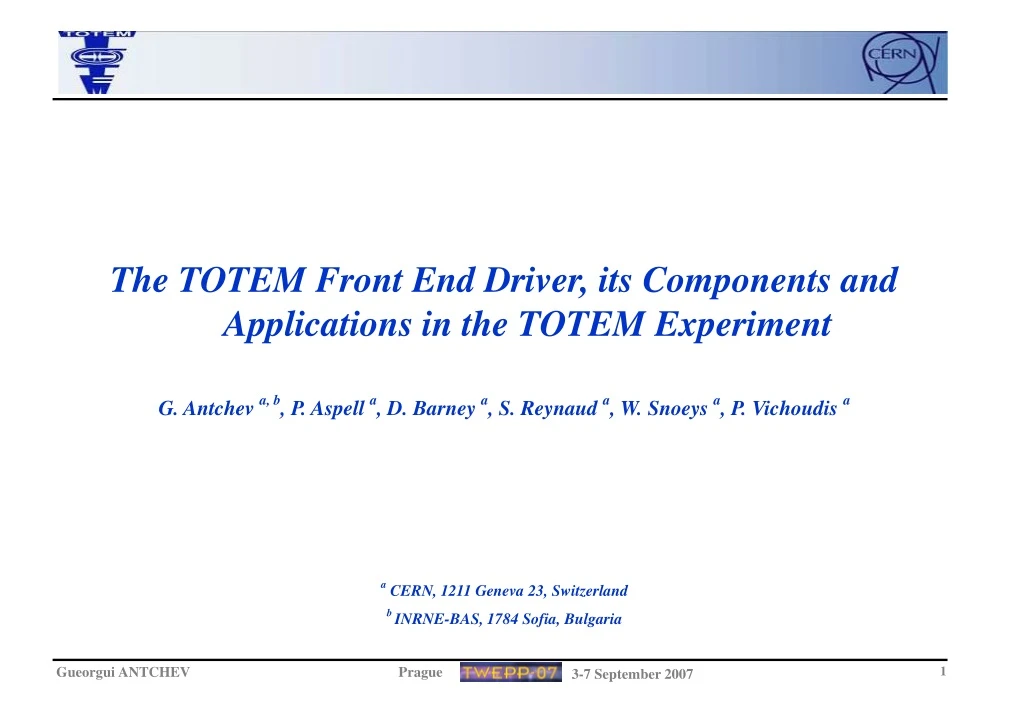
The TOTEM Front End Driver, its Components and Applications in the TOTEM Experiment G. Antchev a, b, P. Aspell a, D. Barney a, S. Reynaud a, W. Snoeys a, P. Vichoudis a a CERN, 1211 Geneva 23, Switzerland b INRNE-BAS, 1784 Sofia, Bulgaria
RPS1 RPS2 RPS3 RPS4 GEM CSC CSC GEM FED FED FED FED FED FED FED S-Link S-Link S-Link S-Link S-Link S-Link S-Link FRL FRL FRL FRL FRL FRL FRL CMS DAQ System TOTEM Electronic System Architecture
General Requirements - The TOTEM Front End Driver (TOTFED) has to receive and handle trigger building and tracking data from the TOTEM detectors; - Interface to the data acquisition and global trigger system; - Modular, based on the VME64x standard; - Very flexible and programmable to deal with the different TOTEM sub-detectors - possible evolution of the data treatment and trigger algorithms over the duration of the experiment - Acquire on-detector data from up to 36 optical links and: - perform fast data treatment (data reduction, consistency checking, etc...); - transfer to the next level of the system; - store data on request for slow spy readout via VME64x or USB2.0. - Compatible with CMS: - permit TOTEM to run both standalone and together with CMS
TOTFED and CMS Preshower DCC - motivation • Similarities: • Common input (GOL) • Common output (Slink mezzanines to the CMS DAQ) • Similar architecture (VME system, spy memories on board) • Problems (use of ECAL DCC seems inconvenient for Preshower / not possible, for different • reasons) • Differences: • 1 S-Link64 per 9 GOLs (TOTEM) vs. ~ 1 S-Link64 per 36 GOLs (Preshower) • Data Reduction on-board for Preshower • Possible Data taking for TOTEM before the other experiments @ low trigger rate (few kTriggers/sec) – USB2.0 can be used for readout • CMS Preshower: • Has the experience in gigabit optical receiving systems and in USB2.0 interface • TOTEM: • Has the experience in VME64x designs, Memory Interfaces and complex system design • Result: • Design of the TOTEM FED in such a way that can be used also for CMS Preshower • CMS Preshower supports the development of the gigabit optical receiver and USB parts.
TOTFED – Components VME64x Host Board: - 9U VME64x Slave Module - Accepts several mezzanine modules OptoRX12: - Custom 12 Channels Optical Receiver Module for GOH - Accepts CMC Transmitter Module CMC Transmitter Module: - CMS DAQ Standard parallel data transfer module - Using S-Link64 interface
TOTFED – Block Diagram and I/O Interfaces Block Diagram Gigabit Optical INPUT 640Mb/s/fiber x 12 = 7.68Gb/s VME64x OUTPUT 40MB/s BLT S-Link64 OUTPUT 480MB/s 64bit@60MHz USB2.0 OUTPUT 480Mb/s – high 12Mb/s – full 320Mb/s – effective S_Link64 OUTPUT 480MB/s 64bit@60MHz Data Bandwidth – by definition TOTFED has: INPUT - 3 x OptoRX -> 3 x 7.68Gb/s OUTPUTS - 4 x S_Link64 -> 4 x 480MB/s - 4 x USB2.0 -> 4 x 320Mb/s - 1 x VME64x -> 40MB/s TOTEM Experiment Trigger Rate - 1 kHz (TOTEM alone) Event Size - 40 kBytes
VME64x Host Board • Main Characteristics: • - 9U VME64x Slave; • Local Bus Master 32bits/40MHz; • 18MB Spy Memory: • 3x 6MB per 12 optical channels • (1 OptoRX), 96bits at 80MHz; • 3x Main Bridge + Memory Controller; • 3x USB 2.0 Interface; • Merger + 6MB Memory + 4th USB; • TTCrx, QPLL and CCS clocks • (optical or electrical); • TTS copper link; • JTAG controller on board; • Connectors for: • - 3x OptoRX; • - 1x DRM or Trigger Mezzanine; • - 3x S-Link64 + 1x S-Link64 on rear • at 200MB/s; • - 2x Optional Board Connectors; • - Boardt0measurements VME64x Host Board
OptoRX12 and S-Link64 • OptoRX12: • - 12-channel digital optical receiver by NGK; • Altera Stratix GX EP2SGX60 device with embedded • hardware de-serializers for up to ~3.2Gbps; • - Connect via five 64pin connectors to the VME board; • - Has connectors for “CMC Transmitter” module • CMC Transmitter: • CMS DAQ standard; • - 64bit electrical transmitter using S-Link64 protocol; • Altera Acex family device
Readout Crate TOTFED TOTFED TOTFED CAEN TTCVI FEC TOTFED in Readout System • TOTFED is set of: • “VME64x Host Board”; • 3 x “OptoRX12” modules; • 3 x “CMC Transmitter” modules • - 2 x “Optional” modules • TOTFED in the Readout Crate
TOTFED Data Format VFAT2 Data Format “CMC Transmitter” CMS Data Format
Trigger Crate TRIG TRIG GLOBAL TRIG CAEN TRIG TRIG TRIG LV1A TOTFED in Trigger System Based on VME64 Host Board Electrical Outputs To “Global Trigger Board” 36 Optical Inputs “Trigger Board” - 36 Optical Inputs; - Algorithms inside Main 1-3 and Merger FPGA; - Data on P2 rear private to “Global Trigger Board” “Global Trigger Board” - On P2 rear inputs from several Trigger Boards; - Mezzanine to send LV1A
Applications and Documentation Applications - TOTEM experiment “TOTFED” – Front End Driver; “TOTFEDTC” – FED Tester Board; “TOTRIG” – Trigger Board; “GLTOTRIG” – Global Trigger Board - CMS experiment “ES-DCC” CMS Preshower Data Concentrator Card; PCB Information on EDMS: see the links: –> “VME64 Host Board” –> “OptoRX12” –> “CMC Transmitter” Technical Information: - Documentation; - Firmware; - Software; - Boards Status; WEB site on preparation
TOTFED - Status Status - Produced and Mounted - 6 pcs; - Under Test - 3 pcs; - Explore final production possibilities - about 90 pcs. total Results - Up to now no major issues, few errors were fixed; - Power Supply Voltages - 3.3V, 2.5V and 1.5V are O.K. - Internal Clock Distributions System for 40MHz and 80MHz works; - External Clock Distributions System works; - From on-board JTAG Devices (FPGA’s, PROM’s and TTCrx) all 18 are accessible via JTAG connector; - “VME64x Slave Controller” FPGA – tested: Internal Registers (Board ID, Control, etc.) and Local Bus W/R access and BLT W/R; - “MAIN Controller” FPGA – programmed and tested: - “CMC Transmitter” on rear tested; - CCS/TTS copper link tested (CMS Preshower group); Basic Test Lab VIEW VI using CAEN1718 USB-VME
Summary VME64x Host Board: - Needs to cover several different requirements for TOTEM and CMS; - Based on modular principle, therefore: - Easy to develop and test separate mezzanines; - Create not fully equipped unit (cost, performance); - Easy to upgrade, replace/redesign mezzanines - Interconnectivities, Connectors and Plug-in TOTFED: - Complex system; - Successfully built; - Progress in testing and using it TOTFED Applications: - TOTEM - Data Readout and Trigger Systems; - CMS Preshower - Data Readout System “ES-DCC” module built and tested in Test Beam 07; - Interest from other experiments in using it