Download
1 / 60
610 likes | 816 Views
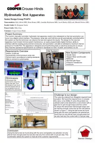
Design Review UL Vibration Test Apparatus. February 21, 2013 11:30AM Est. Project & Team Information. Project: UL Vibration Test Apparatus Project Number: 13471 Customer: Eaton Corporation (previously Cooper Crouse-Hinds Industries) Customer Contacts: Joe Manahan Ed Leubner

E N D
Design ReviewUL Vibration Test Apparatus February 21, 2013 11:30AM Est.
Project & Team Information Project: UL Vibration Test Apparatus Project Number: 13471 Customer: Eaton Corporation (previously Cooper Crouse-Hinds Industries) Customer Contacts: Joe Manahan Ed Leubner RIT Faculty Guide: Dr. Benjamin Varela Project Team: Walter Bergstrom Sean Coots Spencer Crandell Mark Ellison UL Vibration Test Apparatus
Presentation Overview • Systems Level Design Review Overview • Calculation of Deflection Force • Final Design • Adjustment Mechanism • Linear Motion Mechanism • Crank Arm • Frame Design • Drive System and Motor Selection • Lubrication • Test Plan • Cost Breakdown • MSD II Schedule • Questions for Customer • Open Discussion Appendix: UL Test Stand and Project Background UL Vibration Test Apparatus
Systems Level Design Review • Discussed Designs: • Eccentric Shaft • Scotch Yoke* • Crank Arm* • *Adjustment Mechanism • Key Action Items: • Develop adjustment mechanism for fine adjustment of eccentricity • Go ahead with the development of Scotch Yoke • Actions Taken: • Adjustment Mechanism refined after multiple design iterations • Development of Crank Arm with Adjustment after feasibility issues arose over lubrication of Scotch Yoke UL Vibration Test Apparatus
Force Applied to Deflect Luminaire Equations of relative motion were applied to derive the acceleration of the desired deflection assuming a constant angular velocity of the primary shaft. The moment of inertia was than approximated for the conduit with a 100lb cylinder at its end. Assuming the system acted as a pendulum and using the moment of inertia and acceleration we acquired a force. This was then superimposed with the force needed to bend the conduit (cantilever pipe) to the proper deflection. The calculated force was approximately 400lbf. Assuming a factor of safety of 2, the force acting axially on the slider mechanism was approximated at 800lbf. UL Vibration Test Apparatus
Free Body Diagram (eccentric w/crank) 800 lbf UL Vibration Test Apparatus
Crankshaft Analysis A solution to an engine crankshaft force analysis was applied to our problem. The piston side-wall force is the lateral force on the slider mechanism, and the pressure force is replaced with the 800lbf axial force due to the vertical conduit. Courtesy of Dr. Boedo UL Vibration Test Apparatus
Force Equations Maximum Forces on Crankpin: Courtesy of Dr. Boedo UL Vibration Test Apparatus
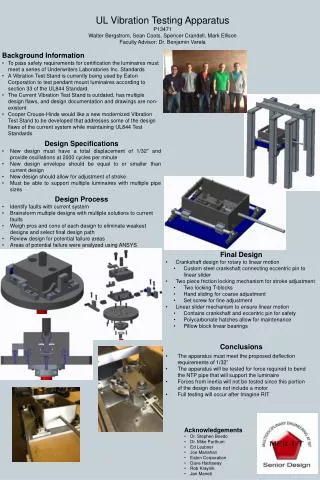
Final Design UL Vibration Test Apparatus
Adjustment Mechanism • Allows for adjustment in eccentricity in order to account for tolerance stack-ups and wear • Allows for verification and adjustment of deflection • Set screw used for fine adjustment • Alignment blocks allow for the measurement of adjustment using calipers • Two socket head cap screws for locking the system in place • Nord Lock washers to prevent loosening of adjustment mechanism UL Vibration Test Apparatus
Adjustment Mechanism UL Vibration Test Apparatus
5/8-11 Nord Lock Washers • Rated for maximum locking at 197 ft-lbs with 20900lb clamping force • Allows for reusable hardware pelicanparts.com UL Vibration Test Apparatus
Adjustment Mechanism Calculations • Assumptions: • Rigid connection between bed and disc surface • θ = 45°; sin(θ) = cos(θ) = • Worst-case loading along the plane of motion for slider at maximum N value (N1200lbf) • Dry steel: μs=0.8 (via engineeringtoolbox.com) UL Vibration Test Apparatus
Adjustment Mechanism Calculations • Required clamping force (each bolt) • Required torque (each bolt) • Where N=1200lbf, μs=0.8, D=0.5” • Assuming simplified estimate: UL Vibration Test Apparatus
GFEM of Adjustment Mechanism • \ • Elements: 41159 • Nodes: 72467 • 1200 lbf bearing load on pin • 1800 lbf bolt pretension on locking bolts UL Vibration Test Apparatus
Von-Mises Stress UL Vibration Test Apparatus
Von-Mises Stress UL Vibration Test Apparatus
Adjustment Mechanism Displacement UL Vibration Test Apparatus
Linear Motion Mechanism UL Vibration Test Apparatus
Linear Motion Mechanism • Keeps mechanisms enclosed for safety • Prevents contaminates from getting into mechanisms • Polycarbonate maintenance hatches on top and side of mechanism • 1” diameter extension rod allows for more robust design without concern of buckling UL Vibration Test Apparatus
Linear Motion Mechanism Calculations UL Vibration Test Apparatus
Linear Motion Mechanism Calculations • Refer to Appendix A of handout for E, I, Sy, A • Assumptions • Rail deflection assumes a single load at the center of the rail (worst-case scenario) • For buckling: C=4 (rigid end and free slider connection) • N=1200lbf, msliderg=115lbf, l=22.25in • Equations via Shigley’sMechanical Engineering Design UL Vibration Test Apparatus
Connecting Rod • Peel-Away Brass Shaft Shims • Shaft collars for holding bearings in place UL Vibration Test Apparatus
Connecting Rod Analysis UL Vibration Test Apparatus
GFEM Analysis of Connecting Rod Loading Case 1 • Elements: 65557 • Nodes: 108327 Loading Case 2 UL Vibration Test Apparatus
Von-Mises Stress • Load Case 1 • Load Case 2 UL Vibration Test Apparatus
Frame Design 34” 44” UL Vibration Test Apparatus
Frame Design Advantages: • Allows for a single technician to mount the luminaire • Extra support of U-channel decrease vibration of system • Rubber pads in-between supporting beams help in dampening the system • More space efficient than current design • *Approximately 44” X 34” footprint • Footprint may become larger due to resonate frequency of design (to be tackled by next senior design group) UL Vibration Test Apparatus
Motor Selection • 3-Phase, 240V AC Motor • Steady-state period • No acceleration of system • lbfft • This corresponds to a motor horsepower of 0.41,therefore a 1hp motor is desired • Where r= in (stroke of crank), θis angle of rotation of the motor ( • Start-up period • Where: • Assuming 50-60 seconds to reach 2000RPM, Treq3 lbfft UL Vibration Test Apparatus
At 2000RPM, a general purpose 1HP AC Baldor motor will produce 90ozft 5.7lbft torque • Our estimated range for required start-up torque is highlighted in yellow • At ~5.7lbfttorque, it is estimated that 2000RPM will be reached in approximately 30 seconds • A variable-frequency drive will be used to obtain the required 2000RPM speed UL Vibration Test Apparatus
Recommended Motor UL Vibration Test Apparatus
Where ka, kb and kc are Marin factors for surface condition, size, and loading conditions, respectively. • l1=2 , l2=4 , σmin, σmax, Sy, Sut can be found in Appendix UL Vibration Test Apparatus
Lubrication • Drive Shaft Bearings: Double sealed flange mount bearings with easy access grease zerk fittings. • Linear Bearings: Double sealed closed bearings with easy access grease zerk fittings. • Crank Arm Bearings: Double Sealed roller bearings pre-packed with grease . Easy access for lubrication by taking off Polycarbonate cover. UL Vibration Test Apparatus
Test Plan • Test the deflection of the pipe • Dial gauge • Measure required torque using torque wrench • Flanged collar mechanism UL Vibration Test Apparatus
-Brinkman Lab Machining: $90 per hour -Only part of the frame may be developed for test purposes -Unexpected tooling costs that may arise -Need for remaking parts (we are not expert machinists) UL Vibration Test Apparatus
Questions For Customer • NPT Pipe Length • Pipe Collar • Testing with Lamp • Financing logistics of Project UL Vibration Test Apparatus
Open Discussion • Any questions? • Design concerns not discussed? • Feed back on work done to this point? • Validity of our Design? • Do we have approval to purchase materials and begin developing the product? UL Vibration Test Apparatus
Appendix UL Test Standard and Project Background
Project Background • To pass safety requirements for certification the luminaires must meet a series of Underwriters Laboratories Inc. Standards. • A Vibration Test Stand is currently being used by Cooper Crouse-Hinds to test pendant mount luminaires according to section 33 of the UL844 Standard. • The Current Vibration Test Stand is outdated, has multiple design flaws, and design documentation and drawings are non-existent. • Cooper Crouse-Hinds would like a new modernized Vibration Test Stand to be developed that addresses some of the design flaws of the current system while maintaining UL844 Test Standards. This new Design must also have a LabView interface and control capability integrated into the system. UL Vibration Test Apparatus